
7W single-stage PFC LED lighting design with TRIAC brightness adjustment
Summary
This report describes the reference design for a 7W AC/DC LED lighting driver with TRIAC dimming. The solution uses a single-stage power factor correction (PFC) inverting topology with primary side constant power control. The article introduces you to the complete analysis and design of power converters. Finally, we also provide you with experimental results based on 7W applications. Simple modifications to the design make it suitable for other applications.
1 Introduction
The PMP4304A reference design is a TRIAC brightness-adjusting single-stage power factor correction LED driver using TI's TPS92210 LED lighting power controller. This LED application is mainly for PAR bulb replacement, which has small volume, low cost, high PF and high TRIAC brightness adjustment performance.
The solution uses a single-stage power factor correction (PFC) inverting converter with primary side constant power control. It achieves primary side constant power control in a single-stage inverting topology without an optocoupler. This driver can be operated with high line voltage AC or low line voltage AC. The output provides a constant current of 350mA to drive six LEDs in series.
2, working principle
2.1 Power Factor Correction Single Stage Inverting Converter
This single-stage power factor correction converter uses an isolated inverting AC/DC topology that rectifies the AC input line voltage to a DC output that inputs the sinusoidal current. Single-stage inverting topologies are widely used as isolated LED solutions because of their very low BOM cost and high efficiency.
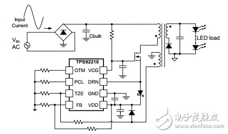
Figure 1 Single-stage inverter
Traditional single-stage inverting solutions use a conversion mode to adjust constants on time to implement PFC functionality. However, the inverse topology of the conversion mode is not a natural PFC because the duty cycle and frequency often change. Therefore, the accuracy of PF and THD under such conditions is not high.
However, the primary side constant power single-stage inversion is a natural PFC.
First, the input voltage can be set to:
![]()
Then, Equation 2 can be used to calculate the average input current.
![]()
With Equations 1 and 2, the input power is calculated as follows:
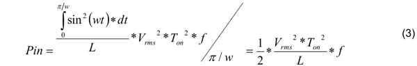
On the primary side, the constant power scheme is:
![]()
In Equation 4, K is a constant and the value of K depends on the total power of the system.
When the RMS of Vin changes, the duty cycle changes inversely. When the RMS of Vin is limited, the duty cycle does not change. Therefore, when the system is stable, the duty time and duty cycle are constant.
At the same time, in order to maintain constant power, the system remains at the same switching frequency.
Since Ton, L, f, and Vin are all constant, the input current is the natural sine of Equation 2.
On the other hand, the input power is also a constant of Equation 3.
In summary, we can see that in this application, the primary side constant power single-stage solution has certain advantages compared to the traditional solution. First, the primary side constant power scheme is a natural PFC with both PF and THD superior to conventional solutions. Second, as the name suggests, the primary side constant power scheme is only controlled by the primary side. Therefore, the optocoupler can be excluded to achieve a low cost BOM.
2.2 TPS92210 controller and system operation
As far as the TPS92210 controller is concerned, there is an OTM pin that can control the Ton time by connecting its resistors; details are as follows:
![]()
In order to achieve primary side constant power control, we use the following circuit, as shown in Figure 2.
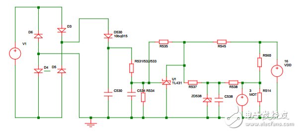
Figure 2 Feedforward circuit for primary side constant power control
Assuming Vin_rms = x, the relationship between Ton and Vin_rms can be calculated as follows:
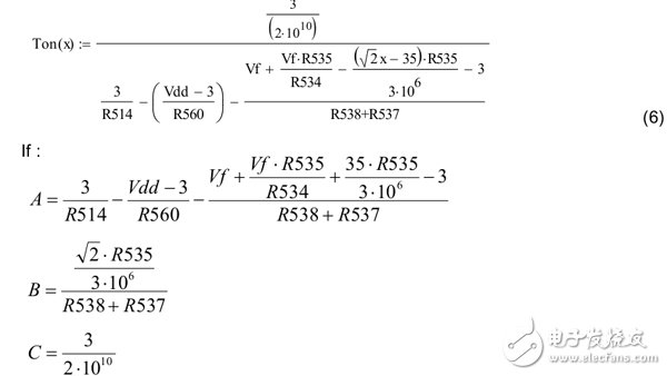
This formula can be abbreviated as Equation 7:
![]()
In order to meet the requirements of primary side constant power control (Vrms *Ton = K), select B=0. At the same time, A and C can be selected according to the input power.
Figure 3 shows the simulation results after 7W calculation. The Ton time becomes smaller as the input voltage becomes higher. At the same time, the input power must remain constant.

Figure 3 Ton time vs Vin_rms and input power vs Vin_rms
Antenk Box Header Connector,Those products are used in more or less every known application within computer-, industrial-, telecommunication and specific automotive markets. This product technology allows cost effective connections between printed circuit boards based on removable or permanent connections based on a longterm proofed way of assembly. Box Header connectors are available with the traditionally used pitch of 2.54mm and the pitch of 2.00mm,1.27mm.
Antenk Box header/Ejector Header Description and Application:
Box header/ ejector header connector, With DIP straight/vertical, SMT,Right angle, 2.54pitch, 2.0pitch, 1.27pitch,
The commonly used Pin ways have 6P,8P,10P,14P,16P,20P, 24P,26P,30P,34P, 40P,50P,64P.
Box header/ ejector header and IDC Flat Cable connectors are two of the most commonly used connectors. Box headers can be found in nearly all electronic equipments.
This is a IDC product which allows cost effective connections between circuit boards based on permanent connection (using transition connector) or removable connection
(Using for IDC flat cable connectors).
Box header

Ejector header

Box Header Connector
Box Header,Box Header Connector,Ecu Box Header Connector,Latch Box Header Connector,1.27mm Box Header Connector,2.00mm Box Header Connector,2.54mm Box Header Connector
ShenZhen Antenk Electronics Co,Ltd , https://www.antenk.com