
A single power supply can control multiple loops
In the power conditioning process, although there are some problems in controlling multiple loops at the same time, if we can understand the constraints of the system, we can come up with a feasible strategy.
In my career, most of the power supplies I designed have a fixed adjustable voltage that can be single input and single output. However, in many cases, it is necessary to adjust not only the output voltage.
For example, when using a light emitting diode (LED) driver, we are usually able to control the current of the LED. In battery chargers, we usually need to limit the charging current until the battery reaches a preset voltage threshold; then adjust the voltage. The USB port can only support and pass a certain amount of current, and the specific current amount varies depending on the application. In these cases, it is necessary to limit the input current. There are many examples of how to implement these functions. Let us refer to the following examples.
The first example is a battery charger whose output current is regulated to a certain level during fast charging. The battery voltage is then regulated primarily by a voltage loop. Figure 1 shows a block diagram of an isolated flyback battery charger.
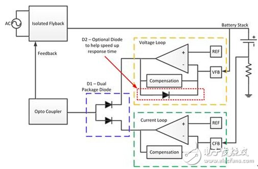
Figure 1: Isolated Flyback Charger for Charging the Battery
During operation, only one control loop is active because the two loops are diodes that are connected by D1 through a logical operator "or". This approach has several advantages: First, both loops provide very precise adjustments; second, each loop can be individually compensated to ensure the stability of both loops. During the voltage regulation phase, there is an additional electrode in the power stage (the electrode is not present during the current regulation phase). However, during rapid state changes, the inadequacies of this approach also emerge.
When the power supply is operating in current regulation mode, the voltage amplifier output level can be pulled high by the rail. If the battery is removed, the current will suddenly decrease and the voltage loop will take over the control task. Since the amplifier and compensation take time to respond, the power supply output will overshoot. If the compensation is adjusted to increase the mid-band loop gain, the overshoot can be reduced. Another option is to add an additional diode from the output of the amplifier for reference (Figure 1, D2). This helps clamp the amplifier's output voltage to a lower value, preventing saturation and speeding up the response. The separate references and soft circuits that need to be added are another disadvantage of the method of using multiple external amplifiers, as this adds to the complexity and cost of the system.
The second example comes from a boost converter - designed to draw power from a USB port. The USB port provides 500mA, 1A, 1.5A and even up to 3A for different types of interfaces. If an accessory attempts to draw too much current, it can overload the bus and cause the port to overheat or shut down the host device. One primitive approach is to monitor the input voltage and wait for it to fall below a certain threshold before reducing the load current. Although this method is feasible, it is not ideal. If the port contains a USB switch, this method may cause the port to be continuously reset. If the current is not limited, it will cause the power to be acquired to exceed the range that the host can support. Another way to solve this problem is very similar to our battery charger example. However, this time we will adjust the input current and output voltage. Figure 2 shows a block diagram of a boost converter with limited input current.
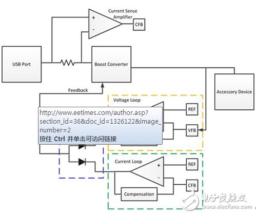
Figure 2: USB boost converter with adjustable input current
This circuit has exactly the same advantages and disadvantages as the first example. It is worth noting that because this is a boost converter, it is especially tricky to have multiple loops. In addition, in this case, since the current is not referenced to ground (GND), we need to add another current sense amplifier. Figure 3 shows the advantages of this circuit to accurately regulate the output voltage and input current. The output voltage is set and can be adjusted from a USB input (where the voltage is 9V). Four curves for different input current regulation settings (500mA, 1.5A, 1.8A, and 3A) are also shown.
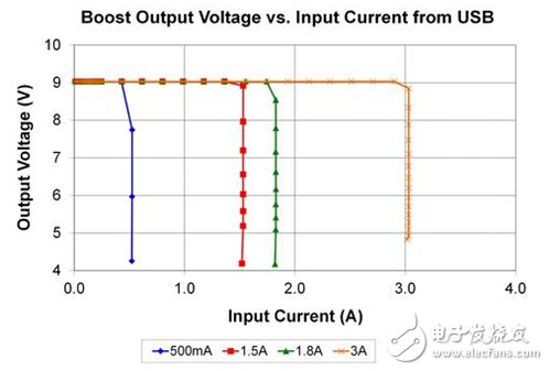
Figure 3: Input current and output voltage are strictly regulated
The last example is a circuit that limits the input current during startup and then adjusts the output voltage. This type of circuit can be very useful when it is necessary to charge a large output bank of a capacitor. The first two circuits use multiple external amplifiers to regulate the current and voltage loops, and most controllers include an integrated voltage loop amplifier (which can still be utilized). Figure 4 shows how to use the output of the built-in error amplifier and compensator to reduce the number of external parts necessary. The basic operating principle is that the output level of the voltage amplifier can be pulled down when the current loop is in operation. When the current loop is inactive, its output level goes high and does not affect normal operation. It should be pointed out that this solution still has this shortcoming that requires an external reference.
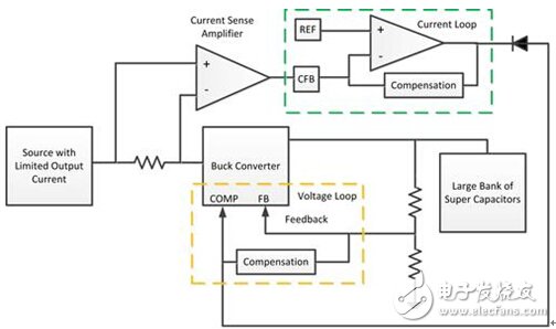
Figure 4: Step-down converter that can charge a supercapacitor
references
OF: John Betten, "LED buck regulator having a current-mode control of the compensation process can be simplified."
About the author: At Texas Instruments, Robert Taylor is an applications manager for Power Supply Design Services and a member of the technical backbone team. Taylor earned his MSEE and BSEE from the University of Florida in Gainesville.
In electrical distribution, a fuse cutout or cut-out fuse is a combination of a fuse and a switch, used in primary overhead feeder lines and taps to protect distribution transformers from current surges and overloads. We make available these fuses in varied specifications to meet the clients' different preferences in an efficient manner. China Service Cut Out Fuse,Porcelain Polymer Fuse Cut Out manufacturer, choose the high quality Porcelain Electric Fuse Cut Out,Porcelain Cut Out Fuse, etc.
| MAIN DIMENSIONS AND STANDARD PARTICULARS | ||||
| Type | RLF-5 | RLF-5 | RLF-9 | RLF-9 |
| Rated Voltage,KV | 15-27 | 15-27 | 24-27 | 24-27 |
| Rated Current,A | 100 | 200 | 100 | 200 |
| Breaking Current,A | 10000 | 12000 | 8000 | 10000 |
| Impulse Voltage,KV | 125 | 125 | 150 | 150 |
| Power-Frequence withstand Voltage,KV | 45 | 45 | 65 | 65 |
| Creepage Distance,MM | 355 | 355 | 505 | 505 |
| Weight,KG | 8.8 | 8.8 | 12 | 12 |
| Dimension,CM | 51.5x34x12 | 51.5x34x12 | 48x34.5x14 | 48x34.5x14 |


We warmly welcome friends both domestic and abroad to visit our company, if you have any questions, please contact with us directly.
Porcelain Cut Out Fuse
Service Cut Out Fuse,Porcelain Polymer Fuse Cut Out,Porcelain Electric Fuse Cut Out,Porcelain Cut Out Fuse
FUZHOU SINGREE IMP.& EXP.CO.,LTD. , https://www.cninsulators.com