
Commonly encountered errors in the use of popular science power filters
During the experimental test, we often encounter the situation that although the design engineer connected the power filter on the power line of the device, the device could not pass the “conduction disturbance voltage emission testâ€. The engineer suspected that the filtering effect of the filter was not Well, constantly changing the filter, still can not get the desired effect.
The reasons for analyzing the equipment exceeding the standard are nothing more than the following two aspects:
1) The harassment caused by the equipment is too strong;
2) The filtering of the device is insufficient.
In the first case, we can solve this by taking measures at the source of the disturbance to reduce the intensity of the disturbance, or increase the order of the power filter and improve the filter's ability to suppress the disturbance. For the second case, except for the poor performance of the filter itself, the filter is installed on it.
The performance impact is great. This is often overlooked by design engineers. In many tests, we can change the way the filter is installed.
Make the device pass the test. Below are some examples of common filter error installation methods that affect filter performance.
1 input line is too long
Many devices' power cords enter the chassis and are connected to the input of the filter after a long wire. For example, the power cord is input from the rear panel of the chassis, travels to the power switch on the front panel, and returns to the rear panel to connect to the filter. Or the filter is installed farther away from the power line inlet, causing the lead to be too long. As shown in Figure 1.
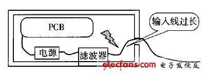
Figure 1 Power cable is too long
Since the lead from the power inlet to the input of the filter is too long, the electromagnetic disturbance generated by the device is recoupled to the power line through capacitive or inductive coupling, and the higher the frequency of the disturbance signal, the stronger the coupling, causing the experiment to fail.
2 filter input and output lines parallel lines
Some engineers often bundle cables together in order to make the internal wiring of the chassis beautiful. This is not allowed for the power cable. If the input and output lines of the power supply filter are paralleled or bundled together, due to the distributed capacitance between the parallel transmission lines, this routing method is equivalent to connecting a capacitor between the input and output lines of the filter for disturbance. The signal provides a path that bypasses the filter, causing the performance of the filter to drop dramatically, even at high frequencies (as shown in Figure 2). The size of the equivalent capacitor is inversely proportional to the wire distance and proportional to the length of the parallel trace. The larger the equivalent capacitance, the greater the impact on filter performance.
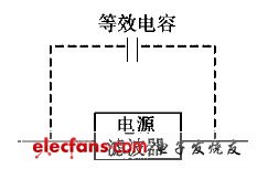
Figure 2 Effect of the flat walking line on the filter
3 The filter is not well grounded, the filter housing is not and gold
Good chassis
This situation is also more common. When many engineers install filters, the gap between the filter housing and the chassis is poor (with insulating paint); at the same time, the grounding wire used is long, which will cause the high-frequency characteristics of the filter to deteriorate and reduce the filtering performance. Due to the long grounding wire, the distribution of the wires at high frequencies
The inductance cannot be ignored. If the filter is well connected, the interference signal can be directly grounded through the housing. If the filter housing and the chassis are overlapped
Poor, equivalent to a distributed capacitance between the filter's housing (ground) and the chassis, which will cause the grounding impedance to be high at the high frequency of the filter, especially
Near the frequency at which the distributed inductance and the distributed capacitance resonate, the ground impedance tends to infinity. The effect of poor filter grounding on filter performance is shown in Figure 3.
As can be seen from Figure 3, due to poor grounding of the filter, the grounding impedance is large and some of the disturbance signal can pass through the filter. In order to solve the poor bonding, the insulating paint on the chassis should be scraped off to ensure a good electrical connection between the filter housing and the chassis.
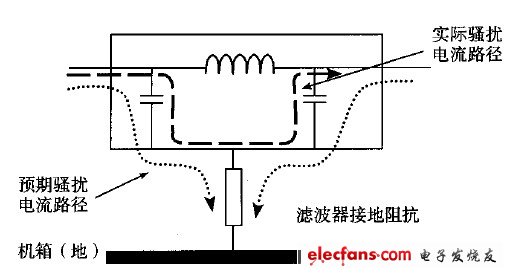
Figure 3 Effect of poor filter grounding on filter performance
Figure 4 shows an ideal example of installing a power supply filter for design engineers.
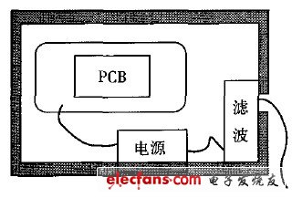
Figure 4 Power Filter Installation Example
In this installation mode, the filter housing and the casing are in good contact, blocking the opening of the power cable on the chassis, thereby improving the shielding performance of the chassis; in addition, the input and output lines of the filter are isolated from each other by the chassis shielding. It eliminates the disturbance coupling between the input and output lines and ensures the filtering performance of the filter.
The installation method of the filter directly affects the filtering effect of the filter. In order to fully utilize the performance of the filter, the following principles should be followed when installing the filter:
1) Install near the power inlet, preferably with a filter housing
Power line inlet hole on the chassis;
2) The shorter the grounding wire, the better;
3) The filter housing is well overlapped with the chassis;
4) The filter input and output lines are separated and cannot be parallel or cross;
5) Avoid strong sources of interference near the filter.
4 Conclusion
This paper mainly introduces the calibration method of electromagnetic pulse sensor under strong field strength. The device under test uses analog optical fiber transmission system to transmit pulse signal, which has the characteristics of low noise, small nonlinear distortion and large dynamic range. The peak response sensitivity to the sensing system was obtained by measurement, and a set of inter-laboratory comparisons showed that this calibration method had good consistency.
The experimental results show that, on the one hand, based on the existing electromagnetic pulse simulator, the pulse electric field that meets the calibration requirements can be generated. In the experiment, the electric field sensor measurement waveform is consistent with the simulation load voltage measurement waveform, and the voltage can be obtained by using a voltage divider. The electric field within the standard device; on the other hand, the calibration data obtained in different calibration devices is consistent. The effect of sensor placement on field uniformity is not considered in this study and will be further evaluated in the next study.
The self-adhesive fabrics are coated with PTFE and have a layer of silicone or acrylic adhesive. The silicone adhesive fabric have a continuous operating temperature range between -70℃ and +240℃. The acrylic adhesive fabrics serves from -40℃ and +150℃ while it offers a very high initial adhesive power and a excellent solvent resistance.
Characteristics:
·easy to apply
·excellent high temperature resistance
·waterproof
·non-poisonous


Adhesive Tapes,Sealing Plastic Film,Sealing Adhesive Tape,Double Sided Adhesive Tape
TAIZHOU YAXING PLASTIC INDUSTRY CO., LTD , https://www.yaxingptfe.com