
Enhance your headphones: noise suppression in headphone amplifiers (Part 5)
In the final installment of the five-part series, I will discuss the noise in the op amp that drives the headphone load and some techniques to reduce the noise. The previous article discussed headphone load power, headphone impedance, and the stability and distortion of the headphone amplifier.
This article refers to the address: http://
The annoying audible noise that occurs when powering up or changing the operating mode in an audio system is often referred to as noise. Due to the high efficiency of the headphone driver, the noise generated becomes a serious problem in the high fidelity headphone system. Even small transients in the signal voltage can create very noisy, annoying sounds in the headphones. To improve the user experience and prevent damage to headphones or other sensitive electronic devices, many systems use circuit science to suppress transient signals generated during amplifier output when power is increased.
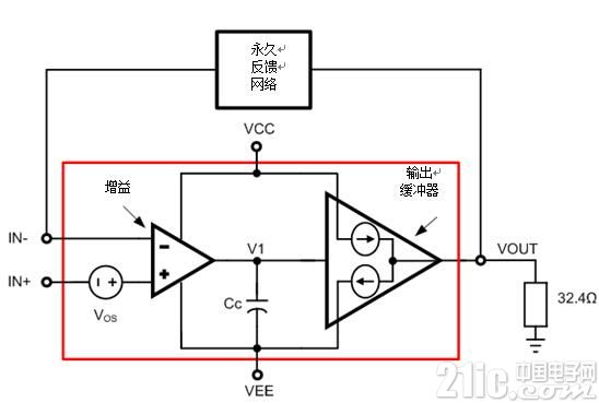
Figure 1: Operational Amplifier Drives Headphone Load
Let's take a look at the common sources of noise in op amps.
Figure 1 is a simplified block diagram of an operational amplifier that drives a headphone load. It consists of two stages - a gain stage and an output buffer, and a compensation capacitor, Cc and a compensation voltage, Vos. As shown, the output buffer is a unity gain stage that sinks current and provides current.
The noise is usually related to the transient at the op amp's output pin. The main sources of noise are:
?? Power ramp: When power is applied, VCC and VEE gradually rise. Before the op amp reaches its minimum power supply requirement, it has not yet reached steady state operation and cannot regulate the output. During this time, a large transient occurs at the output pin. The power supply is disconnected, VCC and VEE may be accompanied by similar transients, and may also cause asymmetric slopes of VCC and VEE.
?? Enable/Disable Amplifiers: Many op amps include the option to enable and disable the device. Enabling the command turns on the op amp's internal bias circuit. As the bias current rises, the gain stage begins to charge the compensation capacitor to the appropriate voltage, the source and sink currents in the output buffer begin to stabilize, and the op amp is near steady state. At this stage, unequal source and sink currents in the output buffer cause current to be injected into the load. This can cause huge noise. A similar transient occurs when the command is closed.
The compensation voltage of the amplifier: The compensation voltage is an interesting source of noise. After the amplifier is near steady state, the output of the amplifier jumps to the compensation of the amplifier (or Vos/β, β = feedback coefficient). If the compensation is large enough, the changes in the output can be heard.
An amplifier with integrated noise suppression significantly simplifies the audio system. The OPA1622 high-performance headphone amplifier includes a solution to suppress noise when the part is in the active or off mode. Figure 2 is a simplified block diagram of the OPA1622.
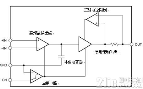
Figure 2: OPA1622 block diagram
The enable circuit (ENC) maintains control of the input and output stages while the amplifier is in the enable or disable mode. When enabled, the ENC can be smoothly converted to drive gain and output stages. When turned off, the ENC can control the charging of the compensation capacitor and disable the gain stage and output stage. Optimizing the transition between in and out mode ensures minimal current injection into the headphone load, minimizing noise.
During the development of the OPA1622, TI focused on optimizing the compensation voltage and the noise it caused. The compensation voltage of the OPA1622 is typically 50μV and the maximum is 500μV.
Figure 3 and Figure 4 show the performance of the OPA1622 during enable and disable, respectively. Only very small output transients are accompanied by a process that is enabled or disabled. Output transients occur for very short periods of time, so it is less likely to be heard when using headphones.
Figure 3: Output voltage with high transient (32Ω) enabled
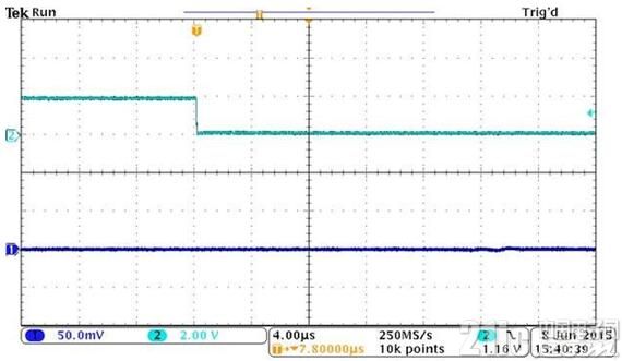
Figure 4: Output Voltage with Low Transient (32Ω) Enabled
There are a number of factors that can affect the noise performance of the op amp that drives the headphones. The OPA1622 enhances the overall user experience in audio applications by using a noise suppression circuit.
Have you ever had noise in your headset system? Welcome to share with TI and let us know about your system design.
We provide quick-turn injection molding by many types of materials, like ABS, PA66, PBT, TPU, TPE, PVC, PE, NYLON 6, PC, silicone, TPE, EPDM, PUR, etc. Special for some plastic parts. Our advantages in internal prototyping, bridge tooling and short-run manufacturing, which can eliminate the costly and time-consuming for customers a lot.
After customer approved 3D drawing, we can test it by 3D printer first, then move on for formal tooling once confirmed ok. And all related materials, logo, color or finishes can be chosed as customers' requirement.
Injection Molding Parts,Plastic Injection Molding,Low Cost Plastic Injection Molding,Plastic Mold Injection Molding
ETOP WIREHARNESS LIMITED , http://www.wireharness-assembling.com