
Hospital care call intercom system design
O Introduction
The hospital nursing call system is an important part of modernized hospitals to realize informationization and modern management, which can effectively enhance the hospital image, strengthen institutional management, and ensure service quality. How to use advanced information technology to serve the hospital and improve the service quality of the hospital to a greater extent is an important focus in the hospital information construction. The call system designed in this paper greatly reduces the labor intensity of medical staff, improves the work efficiency and service level of the hospital, enhances the competitiveness of the hospital, saves management costs, and makes the management of the organization smoother.
1 DTMF call intercom system working principle The whole system schematic is shown in Figure 1. The host and extension of the system are controlled by single-chip microcomputer. The host is connected to each bed through a single bus, and has a call intercom function. When the extension calls the host, the receiver encodes the DTMF and signal sent by the extension into a 4-bit binary code and sends it to the inside of the MCU. After the host receives the extension through the decoder and decodes it, it controls the ringing circuit, the LED display and the LED to indicate the sound. The light prompts that the phone can talk after picking up the phone; when the host calls the extension, the extension receives the number dialed by the host, and the number is compared with the number inherent to the phone. If the number is the same, the phone is connected. The corridor display of the system can display the call bed number, the current number of calls, the call care level, and the real-time time when there is no call.
This article refers to the address: http://

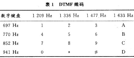
2 Introduction to DTMF Signals Dual Tone Multi-Frequency (DTMF) is a new type of dialing information transmission method. It uses a combination of two audios to encode a dialing key, two of which are respectively separated. From different frequency groups: low frequency group (697 ~ 941 Hz) and high frequency group (1 209 ~ 1 633 Hz), each group of frequencies includes 4 different frequencies, which constitute 16 combinations, representing O ~ 9, * , #, A, B, C and D keys, as shown in Table 1.
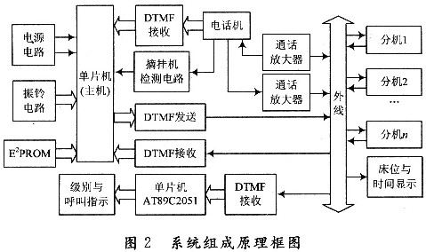
3 system hardware design The call intercom system can be divided into three areas, namely, the medical staff duty room, corridor and ward. The main unit, the telephone, and the display and indicating screens are installed in the duty room of the medical staff. The LED digital tube is installed in the corridor, and the extension is installed in the ward. The system block diagram is shown in Figure 2.
3.1 System working principle The host computer is the core of the whole system. It is responsible for receiving and transmitting the extension and telephone number on the one hand, and controlling the connection and disconnection of the extension and telephone on the other hand. According to the patient's condition, the special protection is set. Class 1 and Class 2 three levels of care, control bed and time display, level and call indication, pick-up machine detection circuit and display display.
In the system, when the extension calls the host, the receiver encodes the DTMF signal sent by the extension, translates it into a 4-bit binary code and enters the inside of the microcontroller. The transmitter then deciphers the 4-bit binary code on the data bus into a DTMF signal output. The host will store the transmitted data; after the data of the CPU is latched, the corresponding digital and bit code is decoded by the decoder, and the extension number and time are displayed by the digital tube; after the phone picks up the phone, the CPU detects the off-hook signal. The ringing signal is cleared, the host talks with the extension, and the host hangs up after the call is completed. When the host calls the extension, after the phone picks up the phone, the CPU receives the dialed extension number after receiving the dialed extension number, and sends the extension number to the extension; if several extensions dial the host at the same time, the host answers the extension with the high level of care and Call, general care level only for display instructions.
3.2 System main hardware design
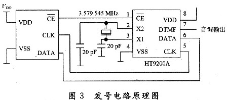
3.2.1 DTMF signal transmission circuit DTMF transmission circuit is mainly undertaken by HT9200A/B. It encodes the 8421 code sent by the host into DTMF signal and then transmits it to the extension or telephone. The numbering circuit is shown in Figure 3.
3.2.2 DTMF signal receiving circuit The receiving circuit is to decode the DTMF signal sent by the telephone into a 4-digit binary code for the host to read. It is essentially a decoding process, and the decoding of DTMF signals is mainly undertaken by MT8870. MT8870 and AT89C52 microcontroller interface circuit shown in Figure 4.
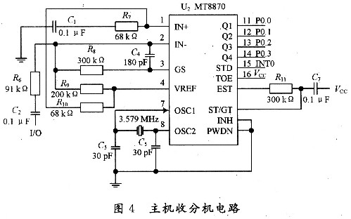
The working principle is as follows: If the MT8870 receives a valid DTMF signal, the EST terminal first goes to a high level, and the control input terminal ST is raised by the integration circuit. If the ST terminal level is lower than the threshold level, the 4-bit binary code inside the MT8870 remains unchanged, and the STD terminal remains low; if the ST terminal is above the threshold level, the 4-bit binary code inside the MT8870 is updated. The STD output changes from low level to high level, and sends an interrupt request to AT89C52, notifying the microcontroller main control station that the control information has been sent. After the AT89C52 receives the interrupt request, it sends it to the STD of MT8870, and the STD end responds accordingly. And through P0. O~PO. 3 Read the decoded data of MT8870, and control the display and indication of the display, LED, etc. according to the content of the decoded data. Invalid DTMF signals (telephone line noise, people's voice signals, etc.) or DTMF signal continuous distortion will not cause the ST88 end of the MT8870 to change.
3.2.3 Pick-up and hang-up detection circuit When the telephone is in standby mode, the 40V DC power supply is the working voltage used by the telephone circuit board. In fact, the voltage at both ends of the telephone is only about 6~12V after off-hook, and the residual voltage falls on the telephone remote communication line. Since the device has a very close line and a small resistance value, a constant current source circuit is provided instead of the high resistance value of the remote communication circuit of the telephone. This is the pick and hang circuit shown in Figure 5.
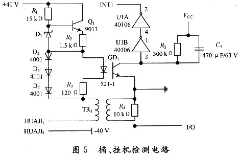
A constant current source circuit is composed of R1, R2, Q1, and D1, and its current is (VD1-VBE1)/R2. The current is forward regulated by D2, D3, and D4 to generate a voltage of 2.1V to provide illumination for the GDl photocoupler. Energy, standby state (on-hook), the HUAJI1 and HUAJI2 nodes of the telephone are open, the constant current source circuit and the optocoupler circuit are not working, the optocoupler is cut off, and the U1A, UlB output is high; the working state (off-hook) is under the telephone. The HUAJI1 and HUAJl2 nodes form a path, and the constant current source circuit and the optocoupler circuit start to work. The current on the left side of the optocoupler is (VD2+VD3+VD4-VGD1)/R3=(O.7+O.7+O.7-1 .8) / 120 = 2.5 mA, to meet the optocoupler operating conditions (1 ~ 50 mA), its internal LEDs emit light, the phototransistor is turned on, and U1A, U1B output low level. It can be seen that off-hook and on-hook can respectively make U1B output different levels, so that the single-chip microcomputer can distinguish the pick-up state of the telephone. The constant current source circuit keeps the operating current of the telephone in the off-hook state at (VD1-VQBE1)/R2=(12-O.7)/1.5=7.5 mA, which satisfies the normal working conditions of the telephone. The MCU determines the pick-up and hook by detecting the high and low levels of INTl.
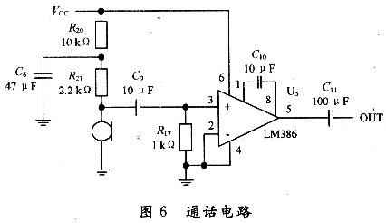
3.2.4 voice call circuit 6 is an enlarged circuit transmits the call signal to the master station, using LM386 low voltage audio power amplifier.
4 Conclusion The research in this paper focuses on designing a practical, low-cost ward care call intercom system. It should be said that the design goal has been achieved through a series of efforts. However, the research on hospital nursing call system is a subject of continuous development. Therefore, it is necessary to further study on this basis, and strive to make the system more perfect, and add functions such as broadcast function, voice report function, and infusion completion warning.