
LED and its driver circuit design basis
Foreword
Lighting has been accompanied by the development of human civilization for thousands of years. From the most primitive drilling wood fire to a wide variety of light sources, such as incandescent lamps, halogen lamps, fluorescent lamps, energy-saving lamps, LED lamps, etc., lighting products continue to develop in an efficient, energy-saving, environmentally friendly, high-tech direction. The birth and development of LEDs provide a high-quality, colorful environment for human lighting. It is widely used in various fields such as civil lighting, industrial lighting, medical lighting, and automotive lighting. With the different application requirements of LED in various fields, LED drive circuits are also constantly improving and developing. This paper introduces, analyzes and forecasts the LED and LED driver circuit design.
LED compared to traditional light sources
LEDs have significant advantages over traditional light sources:
LED illumination is the process of converting electrical energy directly into light. Compared with traditional light sources, such as incandescent lamps, which are first converted from electrical energy into thermal energy, and then converted into thermal energy by the thermal energy, LED has high luminous efficiency and energy saving advantages. In addition, under appropriate driving conditions, LED lamps have a lifetime. Long features.
The LED has a luminous response block, the light source has a variety of shapes, and the color control is flexible.
LEDs have good low temperature properties compared to conventional light sources.
Compared with traditional light sources, LEDs do not contain environmental pollutants such as mercury and lead, so they are more environmentally friendly.
Although LED has a significant advantage over traditional light sources, LED lamps currently have higher cost, and the drive circuit design, optical system, and mechanical design are more complicated.
LED lighting principle
LED–Light EmitTIng Diode LED is a semiconductor electronic component that emits light. LED illumination is an injection type electroluminescence. When a forward voltage is applied to the light-emitting diode, holes injected from the P region into the N region and electrons injected into the P region from the N region are separated from the electrons of the N region and the P region by a few micrometers in the vicinity of the PN junction. The hole complexes to produce fluorescence of spontaneous radiation. The energy states of electrons and holes in different semiconductor materials are different. When the energy released by the recombination of electrons and holes is different, the more energy is released, the shorter the wavelength of the emitted light. The wavelength of light determines the color of the light.
Luminous wavelength: 
Where: h—Planck constant; c—speed of light;  - The forbidden band width of the semiconductor.
The principle of LED illumination is shown in Figure 1:
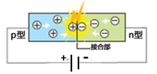
Figure 1 LED lighting principle
LED structure
The basic LED mechanism includes an LED chip, an electrode, a bonding wire, and a whole package mechanical component and optical component such as an LED chip holder, a lens, a silicone, an epoxy resin, a phosphor, and the like.
LEDs are divided into single-chip packages and multi-chip packages. With the development of technology, some of the protection components or part of the LED driver circuit components are also packaged together with the LED chips.
The basic structure of a single-chip LED is shown in Figure 2, Figure 3:
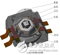
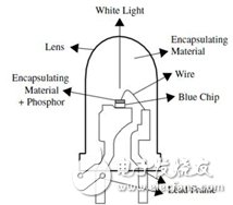
Figure 2 SMD package LED structure Figure 3 plug-in package LED structure
LED main parameters
Electrical parameters
Maximum forward working current IF: refers to the maximum forward current value allowed to be applied to the LED under normal LED operation.
Maximum Surge Current IFM: Allows the maximum inrush current value to be applied to the LED.
Forward operating voltage VF: is the forward operating voltage of the diode obtained at a given forward current.
Maximum reverse voltage VR: The maximum reverse voltage allowed by the LED PN junction.
Rated Power PD: The maximum value of the product of the forward DC voltage applied across the LED and the current flowing through it.
Optical parameter
Peak emission wavelength  p: the wavelength corresponding to the value of the maximum spectral radiation power.
Spectral half-wave width Δλ: 1/2 of the radiant power of the peak emission wavelength corresponds to the interval between the two wavelengths.
Luminous flux Φv: Luminous flux emitted by the optical window of the device when the forward current of the LED is a specified value.
Light intensity: The luminous flux emitted by a point source in a given solid direction in a unit solid angle, in units of candelas (Cd).
The half value angle θ 1/2 and the angle of view: θ 1/2 means the angle between the direction in which the luminous intensity value is half of the axial intensity value and the axial direction of the light emission (normal direction). The half angle value is twice the angle of view (half power angle).
Chromaticity coordinates x, y, z: 1931 CIE-XYZ system, based on the RGB system, mathematically, three ideal primary colors are used instead of the actual three primary colors. Thus the spectral tristimulus values ​​in the CIE-RGB system  And the chromaticity coordinates r, g, b become positive values.
Color Rendering Index CRI: The effect of a light source on the color appearance of an object compared to a standard reference source. In other words, CRI is a measure of color recognition in comparison to a standard source such as daylight.
Color Temperature (TC): When the light emitted by the light source exhibits the same color as the black body radiation at a certain temperature, the temperature of the black body (TC) is the color temperature of the light source.
Metal Film Resistor is Film resistor (Film Resistors) of a kind.It is the high temperature vacuum coating technology will be closely attached to the porcelain nickel chromium alloy or similar bar surface skin membrane, after debugging cutting resistance, in order to achieve the final requirements precision resistance, then add appropriate joint cutting, and on its surface coated with epoxy resin sealing protection.As it is a lead resistance, it is convenient for manual installation and maintenance, and is used in most household appliances, communications, instruments and instruments.
Metal Film Resistors,2W Metal Film Resistors,3W Metal Film Resistor,5W Metal Film Resistor
YANGZHOU POSITIONING TECH CO., LTD , https://www.yzpstcc.com