
LED dot matrix screen design with novel Bluetooth technology
Abstract: Aiming at the problems in the application of LED display, a scheme of low-cost, easy-to-update and convenient dot matrix LED text display is presented. The system adopts C8051F410 as the MCU, and uses the Bluetooth module to receive the data transmitted by the mobile phone Bluetooth, and the data is converted into the character set by the MCU control font chip, and the dot matrix code is extracted, and then the display data is updated by the single chip microcomputer to control the dot matrix screen. After actual use, the control is stable and convenient.
0 Preface
This paper designs a dot matrix LED text display with convenient, scalable, and low price updates. The way to reduce costs is to update the LED display content with the Bluetooth data transmission function of almost everyone's mobile phone, eliminating the cost of professional PC software and control card, and the operation is simpler; 2 single display content is 5 ~ 30 Chinese characters or English letters, because the display content is small, the expansion circuit can be simplified.
1 system design
1. 1 system composition
The system consists of a Bluetooth-enabled smartphone and an LED display. Among them, the LED display consists of a single-chip microcomputer, LED dot matrix module, font chip, Bluetooth receiver module, 5V switching power supply and 3.3V voltage regulator circuit, as shown in Figure 1. The system works as follows: The user edits the “data†through the smartphone's notepad and sends it via the wireless Bluetooth to the Bluetooth receiver module on the display. The main control MCU reads the “data†received by the Bluetooth receiving module and processes it. “Data†consists of “Control Command†and “Display Contentâ€, and the two parts of data are separated by custom signatures. “Control Command†is used to set the brightness of the display, the moving speed of the display content and the moving direction. The MCU finds the corresponding 32-byte display code in the font chip according to the received character code of the “display contentâ€. Screen display.
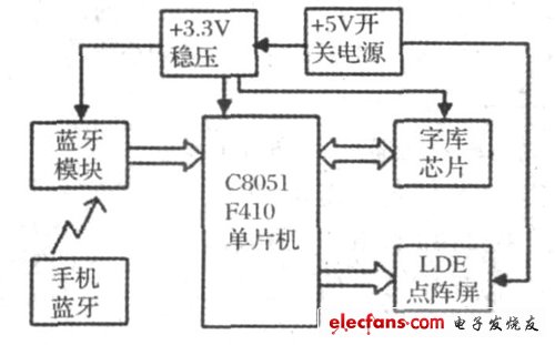
Figure 1 System composition
1. 2 LED dot matrix working principle
The LED dot matrix display can be made up of several pieces of each LED unit board as needed for display. The universal LED unit board consists of 2 digits 16 & TImes; 16 dot matrix LEDs, measuring 160* 320mm2. The unit board works as follows.
Each board has 16 rows and 32 columns, and the data is displayed using traditional determinant scanning. Usually, in order to reduce the flicker and increase the scanning speed, 1 / 4 scanning is used, that is, 16 lines are divided into 4 4 lines, and the same order corresponding rows in 4 4 lines are simultaneously strobed at the same time, so that scanning can be completed 4 times. A 16-line scan is displayed. The column control is carried out by the 74HC595. There are 16 pieces on each unit board, each of which controls 4 rows and 8 columns of dot matrix units. The row control is carried out by a single decoder 74LS138, which strobes the four rows of the same row of the cell board at the same time. To ensure normal current drive (brightness), the output of the 74LS138 is amplified by the AMP4593 driver. There are 4 pieces per cell board, each driving 4 rows. The 16-piece 74HC595 is connected in cascade mode. Since each of the 4 rows and 32 columns requires 4 74HC595, 16 rows and 32 columns are 16 slices. Set the first four rows of four 74HC595 serial numbers 1, 2, 3, 4, the second four rows of four 74HC595 serial numbers 5, 6, 7, 8, and so on. The data output terminal of each chip is connected to the input end of the next chip, and the data is serially input from the input end of the first chip. One bit is sequentially shifted in by the shift pulse, and 8 pulses are received. The data moved in first is shifted to the lowest bit of the 16th chip (also the output of the chip). After all the data is moved in, the complete content of one board can be displayed, and the software design can be displayed according to this rule. If there are more words displayed, there will be more spliced ​​LED unit boards, and more shift pulses are required to display the full contents of one screen. This display mode requires the master microcontroller to have a higher instruction execution speed, otherwise there will be a flickering sensation. The schematic diagram of the lattice unit board is shown in Figure 2.

Figure 2 lattice unit board schematic
2 system main module selection and circuit design
2. 1 master chip
2. 1. 1 chip selection
In order to meet the display of the LED display and the expansion of the multi-board, the system main control MCU needs to have a faster running speed; the larger storage space is used to store the display data, so the C8051F410 of the American silicon company is selected. The chip is a high Performance products, FTQP-32 package (9mm * 9mm) greatly reduced the size; due to the use of a reduced instruction structure, each machine cycle requires only one clock cycle, the operation speed is greatly accelerated, if using on-chip 24. 5MHz The internal clock runs at about 24 times faster than the normal 8051 microcontroller working at 12MHz clock. The chip has rich internal resources and comes with a watchdog. It can be connected to the debugger through the JTAG interface, which facilitates hardware debugging. The chip contains UART and SPI. , I2C and other communication interfaces, easy to connect with peripheral chips; 4 timers / counters make programming more convenient; comes with 16K/32KFLASH, can store about 1K Chinese characters.
| About Copper Bar |
Construction field, ships building industry, petroleum & chemical industries,
war and electricity industries, food processing and medical industry, boiler heat exchange, machinery and hardware fields. Stainless
steel pipe can be made according to the customers requirements.
Standard export seaworthy or as per customers' requirement

|
Machine for Quality. |
We have imported machine for protecting the quality of products.

Copper Bar
Copper Bar,Flat Copper Bar,Oxygen Free Copper Bar,Electrical Application Copper Bar Flat
HENAN HUAYANG COPPER GROUP CO.,LTD , https://www.huaonwire.com