
Micro-pitch QFP device manual soldering guide
Micro-pitch QFP device manual soldering guide
Scope This article attempts to help designers make the first prototype system using Cygnal TQFP and LQFP devices without surface mount equipment. This application note assumes that the reader has at least basic hand soldering techniques for through-hole soldering. This article describes how to remove and clean one. 48-pin TQFP device with 0.5 mm pitch
Safety All work should be done in a well ventilated environment. Exposure to solder fumes and solvents for long periods of time is dangerous. No sparks or flames should be present when using solvents.
Tools and materials Suitable tools and materials are the key to doing the welding work. The following table lists the tools and materials recommended by Cygnal. Other tools and materials can work. Therefore, users can freely choose alternatives. It is strongly recommended to use low temperature solder.
Required tools and materials
1 package wire size 30*
2 Strippers for roll wires*
3 soldering station temperature adjustable ESD protection should support the temperature value of 800 ° F 425 in this case using Weller EC1201A type soldering iron tip to the width of the top of the fine can not be greater than 1 mm
4 solder 10/18 organic core 0.02 (0.5 mm) diameter
5 flux liquid type is installed in the dispenser
6 Tin strip C size 0.075 (1.9 mm)
7 The magnifying glass is a minimum of 4 times. In this example, Donegan Optics' head-mounted OpTIVISOR magnifier is used.
8 ESD pads or desktop and ESD bowls must be grounded
9 pointed not to flat head
10 isopropyl alcohol
11 small hard brush nylon or other non-metallic material used to clean the board to cut the bristles to approximately 0.25 (6 mm)
* Only used when removing the device
Optional
1 wrench for fixing the printed board
2 gingival 90 degree bending
3 compressed dry air or nitrogen for drying the board
4 optical inspection stereo microscope 30-40X

Figure 1. Some of the tools and materials needed

Figure 2. 4X head-mounted magnifying glass suction belt from the left in the clockwise direction
Rolled wire hard cleaning brush stripper and sharp tweezers
Figure 3a. Tin strip and package wire
Figure 3b. Isopropyl alcohol
Figure 4. ESD protection soldering station with a thin tip
This is a Weller EC1201A soldering station

Figure 5. Optional device includes a PCB clamp and
A 7-40X inspection microscope
The procedure below describes the replacement of a 48-pin TQFP device with a 0.5 mm pitch. The lead shape is a standard gull-wing JEDEC-compliant QFP. This section is divided into three sections.
A remove the device
B Cleaning the board
C soldering new device
If you are soldering components to a new board, skip Part A and go directly to Part B to clean the board.
A removal of the device preparation
Mounting the board with the IC to be removed in a holder or wrench. The PCB holder/plate wrench is optional but the PCB needs to be securely fixed in order to remove the device.
Heat the soldering station to 800°F425 cleaning tip
Take ESD protection measures
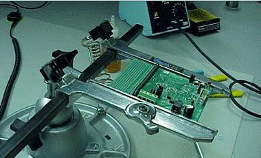
Figure 6. Getting ready to start
First apply the flux on all the pins so that it is easier to remove the solder and remove as much solder as possible from the QFP leads. Be careful not to burn the PCB due to prolonged solder heating.

Figure 7. Solder flux to remove solder from the pins
Next, strip about 3 inches of insulation from the size 30 package wire and cut the wire around 12 inches.

Figure 8. Stripping through the wire as shown in Figure 9. 
Figure 9a. Pass the wire under the QFP pin

Figure 9b. One end of the wire is attached to a nearby component
Fix the end of the 3-inch wire with a solder on a nearby via or component. The mounting point should be in a position similar to that shown in Figure 10.
Apply a small amount of liquid flux to the pins 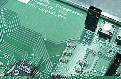
Figure 10. Guide leads attached to C6
Use a pair of tweezers to hold the unfixed end of the free end of the wire so that the wire is against the device as shown in Figure 11.