
New high-light ratio LED driver design high-power lighting solution
One of the reasons for the popularity of LED lighting solutions is that LEDs can achieve a wide dimming range with simple current control, such as automotive dashboards and aircraft cockpits where the ambient illumination may be very low. Wide PWM dimming range. Linear Technology's LT3478 and LT3478-1 are single-chip step-up DC/DC converters that use a constant current to drive high-brightness LEDs over a wide range of settings. In addition to the optional 10:1 analog dimming range, the LT3478 and LT3478-1 feature a 3000:1 PWM dimming range to maintain LED color.
The LT3478 and LT3478-1 are easy to use and have programmable features designed to optimize performance, reliability, form factor and total cost. These devices operate in boost, buck, and step-down LED driver topologies. The amount of LED current they can provide depends on the topology, up to 4A. Ideal for high-power LED applications, including automotive and avionics, the LT3478 and LT3478-1 are available in a 16-pin thermally enhanced TSSOP package with E- or Class I temperature ratings.
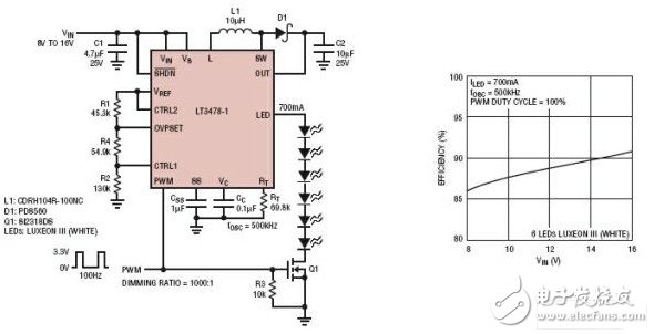
Figure 1: Step-up LED driver circuit for automotive TFT LED backlight applications.
The LT3478 and LT3478-1 operate similarly to conventional current-boost converters, but they use LED current (rather than output voltage) as the primary feedback source for the control loop. Figure 2 shows the main functions of each part. Both devices feature high-side LED current sensing for operation in both buck and boost modes. The LT3478-1 saves space and cost by integrating current sense resistors and limits the maximum LED current to 1.05A. The LT3478 uses an external sense resistor that allows a maximum programmable LED current of 4A.
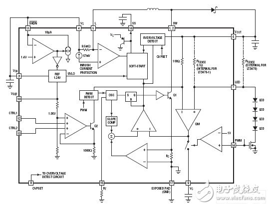
Figure 2: Functional block diagram of the LT3478 and LT3478-1.
Set the maximum LED current
Dimming current control is an important feature, but it is also important to avoid LED overdrive (beyond its maximum current rating). The LT3478 and LT3478-1 make it easy to set the maximum current and reduce the maximum current based on temperature.
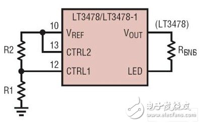
Figure 3: Circuit connection diagram used to set the maximum LED current.
The LT3478 and LT3478-1 use the CTRL1 pin voltage to control the maximum LED current unless the device is set to reduce the maximum LED current based on temperature (using the CTRL2 pin). A simple resistor divider from VREF (see Figure 3) or an external voltage supply can be used to set the CTRL1 pin voltage, or CTRL1 can be tied directly to the VREF pin to provide maximum current. Figure 4 shows the LED current vs. CTRL1 pin voltage.
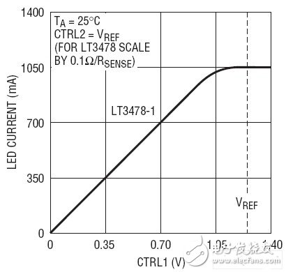
Figure 4: LED current vs. CTRL1 pin voltage.
Reduce maximum LED current based on temperature
To ensure optimum reliability, LED manufacturers specify a maximum allowable LED current versus temperature curve (Figure 5). If the maximum LED current is not adjusted according to the temperature, it may cause permanent damage to the LED.
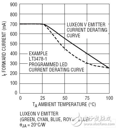
Figure 5: LED current drop curve versus ambient temperature.
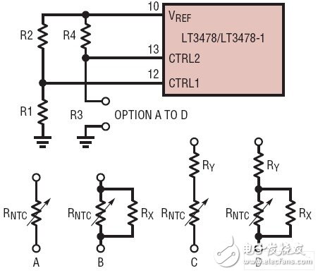
Figure 6: Setting the LED current derating curve versus temperature.
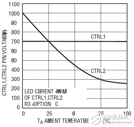
The LT3478 and LT3478-1 use the CTRL2 pin to reduce current. As shown in Figure 6, simply connect the CTRL2 pin to VREF through a temperature-dependent resistor divider. When the temperature rises, the CTRL2 pin voltage drops. When the CTRL2 pin voltage drops below the CTRL1 pin voltage, the maximum LED current is set by the CTRL2 pin voltage (Figure 7).
The temperature at which the LED current begins to drop and the speed at which the current drops are selected by the resistor network/resistance used. Table 1 lists the website information of NTC resistor manufacturers Murata Electronics, TDK and Digi-Key. Murata Electronics Inc. specifically provided an in-circuit simulation program for selecting the desired combination of resistors (shown in Figure 6), including a catalogue describing NTC resistor specifications. Figure 5 shows an example of the LT3478-1 programming LED current drop versus temperature curve, using the alternative C shown in Figure 6, where: R4 = 19.3k, RY = 3.01k, RNTC = 22k (NCP15XW223J0src ). For a more detailed description of how these values ​​can be determined by hand calculations, please refer to the data sheets for the LT3478 and LT3478-1.
Table 1: NTC Resistor Manufacturer/Distributor.
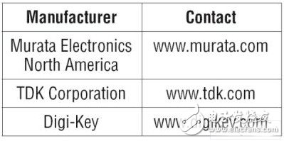
Figure 7: CTRL1 and CTRL2 pin voltage vs. temperature.
  
Connector brand: JST, MOLEX, HIROSE, JWT, DEPHI, TE, Deutsch, Yazaki, Sumitomo, these are very popular
Conector type: board to board connector, wafer connector
Yacenter is professional factory, specialize in wire harness in transportation, medical, house applicance and so on.
We are one of menbership of WHMA with ellecellent team, and pass UL, TS, CE certificate.
We develope high-tech engineering, prototyping, and qualify manufacturing at very competitive pricing for Connector System.
Connector System
Connector System,Cable Harness,Wiring Harness Wire,Custom Auto Wiring Harness
Dongguan YAC Electric Co,. LTD. , https://www.yacenter-cn.com