
P-NET fieldbus technology
1. Introduction to P-NET (IntroducTIon of P-NET)
P-NET field bus technology is researched and developed by Proces-Data A / S Company, and it is a kind of open standardized bus that is universal in the world. P-NET uses a master-slave system, but there are multiple master stations. The first product of the multi-master fieldbus was developed in 1984. Multi-network and multi-port functions were added to the scope of the protocol in 1986.
2. Main characteristics of P-NET (Main characterisTIc)
P-NET is a multi-master master-slave bus (each segment can accommodate up to 32 masters), using shielded twisted pair cable RS485, each segment bus is up to 1200 meters, and each segment can connect up to 125 A repeater is used between the device and the bus segment, and the data is asynchronously transmitted in NRZ encoding, with a transmission rate of 76.8kbit / s.
P-NET can connect all parts of the production process, such as process control computers, sensors, actuators, I / O modules, small programmable controllers, etc., by connecting a two-core cable, as shown in Figure 1. Compared with traditional wiring, P-NET field bus technology has considerable advantages in industrial control. It greatly simplifies design and installation, reduces the number and cost of wiring, reduces the possibility of various equipment failures, and achieves more The function is also more widely used directly.
The P-NET bus provides only one transmission rate, which can be applied to several levels of a complex factory automation system at the same time, and the transmission rate of each level remains the same. The multi-network structure formed in this way eliminates the need for special couplers for communication between the various levels, and enables direct addressing between several bus segments. Any P-NET module, including the master station, can be connected or disconnected from the bus without affecting other parts of the bus. In this way, the modules can be interchanged when the system is running, and the system can be expanded when the system continues to run.
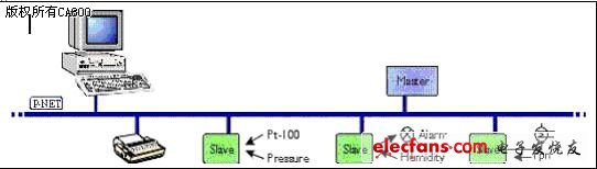
Figure 1 P-NET bus connection diagram
P-NET bus access adopts the "virtual token transfer" method, and the bus access right is transferred between the main controllers through the virtual token. This token transfer method is a time-based cyclic mechanism, which is different from the method of using real messages to transfer tokens. Compared with the message passing token method, it saves the processing time of the main controller and improves the transmission efficiency of the bus, and it does not require any bus arbitration function.
P-NET does not use a dedicated chip, it only requires a few kilobytes of encoding for the slave's communication program. Because P-NET uses the same microprocessor to control the main tasks and communication functions of the node, it saves the dip switch for selecting the baud rate and setting the node address than the independent chip / microprocessor structure. "Small system, low cost" is the main feature of P-NET bus.
The P-NET system can be used to download parameters and programs to the module to control the process. The system can also automatically check for field device and cable faults. Compared with the traditional DCS system, its advantages are: simplified design and installation; reduced cable usage and cost; reduced installation and maintenance costs; making future system expansion more convenient; intelligent P-NET sensors and implementation The device also provides better diagnostic features than traditional circuits.
3. P-NET system structure (System structure)
3. 1 P-NET system structure
The P-NET bus system uses layers 1, 2, 3, 4, and 7 of the OSI "Open System Interconnection" reference model, and uses the channel structure to define the user layer.
The first physical layer: defines the form of transmitting original data bits on the network, and at this layer describes the electrical interface, baud rate, cable, etc. of the system.
The second layer of data link layer: control bus access; generate and identify frame boundaries, identify node addresses; perform error monitoring functions during transmission; used to implement multi-master features, sort the data and send it to the source address or target Address, and troubleshoot.
The third layer of network layer: realize the information transmission of data link layer and service layer, and perform the function of gateway. The network layer is like a P-NET post office, receiving and sending information based on source and destination addresses. A piece of information may be required to be sent from a P-NET website, or sent to another P-NET server, or sent back to the requested device, or returned to the original node.
The fourth service layer: to complete two different tasks, one is to provide P-NET services, read and write data from the internal memory according to the program; the second is to record the number of messages that have been sent and are waiting for a response, when a request is answered Is sent back to the source address.
The seventh layer allows the application to access other device variables. This function is implemented by sending a command block, which contains some reference messages and contains detailed information such as the device address.
3. 2 P-NET network structure
P-NET field bus is a multi-master, multi-network system. The bus adopts a segmented structure, and multiple master stations can be connected to each bus segment, and the master stations can be interconnected on the Internet through an interface. The multi-network structure of the P-NET field bus system is shown in Figure 1.
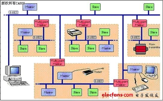
Figure 2 P-NET multi-network structure
In the past, the basic idea of ​​designing automation for factories was to connect the sensors and actuators with a field bus, and then connect the field bus to a unit controller to form a subsystem. The backbone buses are connected and sent to a powerful computer for termination. Therefore, the bus is divided into two levels in principle, one is composed of several low-speed field buses, and the other is connected by a high-speed bus.
P-NET breaks these two different levels and equalizes them to minimize the high-speed and low-speed levels. According to current technology, the requirement for fast data transmission rates at higher levels has been reduced, more intelligence has been dispersed, and a more sensible way to decentralize information processing is the characteristics of P-NET. It can be used at all levels of a plant-wide automatic control system. According to each part of the plant, an automatic control system is divided into several units, so that each unit has such a nature: when this unit is closed, the entire system is not affected Affected, the execution of the program can be distributed independently in one or several processors of each unit. The need for an independent unit to exchange data with other units is very limited. A software or hardware error in one unit will not affect other units.
In a system with real distributed intelligence, additional processing power can always be realized in the form of an additional master station, so such a system can be expanded. Among various feasible field bus systems, only P-NET allows direct addressing on several bus segments, which is also called a multi-network structure. This feature is a special part of the P-NET protocol, and it can be loaded into the standard operating system of a multi-port controller.
Communication is directly transmitted on different bus segments through nodes with two or more P-NET interfaces. This means that any master on a bus segment can “transparently†access any node on any other segment without the need for special programs in the multi-port master. The benefits of dividing a system into small parts are very obvious, because it can limit the impact of errors in a single segment, thereby ensuring higher system security. Not only that, these multi-network features provide a natural redundancy, which makes the entire system very fault-tolerant.
The 1140V mining intrinsically safe and Explosion Proof Drive produced by FGI adopts the IGBT clamped three-level topology. The output voltage waveform is an approximate sine wave formed by superposition, and the higher harmonic components are significantly lower than the two-level inverter`s. The interference to the power grid and control system has improved significantly. This explosion proof Variable Frequency Drive is used in coal mine scraper conveyors, high-power tape conveyor and winch control, etc.
Vfd Variable Frequency Drive,Vfd Ac Drive,1140V Flameproof Vfd,1140V Mine Flameproof Vfd,Explosion Proof Drive,Explosion Proof Variable Frequency Drive
FGI SCIENCE AND TECHNOLOGY CO., LTD , https://www.fgi-tech.com