
TD-MBMS technology and evolution
0, overview
This article refers to the address: http://
The MBMS technology defined in 3GPP is divided into two modes: FDD (for WCDMA systems) and TDD (for TD-SCDMA systems). In the 3GPP R6 version, the high-level protocols and related business processes of TDD MBMS and FDD MBMS are identical, and only slightly different in the physical layer. FDD MBMS technology has basically completed standardization work in the 3GPP R6 version, and TDD MBMS technology continues to be studied in the 3GPP R7 version. TD-MBMS adopts the frame structure of the current TD-SCDMA system. The multiplexing, coding, modulation, interleaving and puncturing of channels follow the existing signal flow specifications. Currently, TD-MBMS is implemented by means of common channels, and wireless over the air interface. The resource application is based on the technical approach of the common channel.
1, TD-MBMS technical characteristics
1.1 Macro Diversity Technology
In the TDD system, the base station requires complete synchronization, which is precisely the advantage of the MBMS point-to-multi-technology. It is one of the main features of the multimedia broadcast service to transmit the same service in multiple cells. If multiple cells can be simultaneously transmitted, the terminal can By combining these wireless signals as useful signals, the transmission power of the base station can be reduced. Compared with the FDD system, since the base stations are asynchronous, in order to ensure that the multi-cell signals can be combined, the base station controller needs to define the cell. The cell group ensures that the delay between the base stations in the cell group is within a certain range, so that the terminal can perform useful signal combining. However, in the TDD system, as long as all stations are guaranteed to carry the same service on the same carrier frequency and the same time slot, the terminal can receive the same service signal of multiple neighboring cells at the same time, and perform macro diversity, thereby improving Receive performance to reduce base station transmit power. Two macro diversity schemes are supported in the TD-MBMS system [2]. First, for MBMS services with the same content, the same content is transmitted at the same frequency point, simultaneous slot, and synchronously, and the same Midamble code and scrambling code are used. Second, for the same MBMS service, the same frequency point, simultaneous slot, and synchronization are used. The same content is sent, but the original scrambling code and Midamble code of each cell are used. In the case where the time slot in which the broadcast service is transmitted adopts the existing intra-frequency network configuration, the configuration of the scrambling code and the Midamble code is still based on the existing network configuration.
1.2 Signal interference cancellation
In the TD-SCDMA system, for the MBMS service, the omnidirectional antenna will be used for omnidirectional coverage in the cell, and the beamforming of the smart antenna for the general R4 service will provide services for specific users, eliminating other The user's signal interference, the users in the non-MBMS service cell will be interfered by the cell that provides the MBMS service adjacently (this is because the beamforming cannot be performed on the MBMS service time slot in the MBMS cell, and the signal is omnidirectional transmission). Therefore, some spatial isolation is required between the non-MBMS cell and the MBMS cell to reduce or eliminate interference.
1.3 Base station adopts random phase deflection technology
In the real network, after the signals received by the UE from multiple cells are superimposed, a deep fading phenomenon of the main wave signal may occur, which may reduce the power superposition gain. Therefore, in order to improve the service quality of the cell, in order to improve the MBMS service quality of the cell, it is considered to introduce different random phase rotations to the transmitting ends of the multiple cells, improve the channel characteristics, improve the power stacking gain, and obtain diversity and interleaving. Gain.
1.4 Flexible Broadcast Area Configuration and Resource Configuration
In the TD-MBMS system, flexible broadcast area configuration is supported. The operator can configure different sizes of broadcast areas for time slots, and select a certain time slot on a certain frequency point to form a network to transmit MBMS services. In addition, the TDD system supports flexible resource allocation. For a relatively fixed service such as a TV channel, a static resource allocation method can be used to configure a corresponding resource when the cell is established. For a random service, a resource can be allocated before the service is initiated. Release after the end, so that you can make full use of system resources.
2. MBMS overall architecture plan
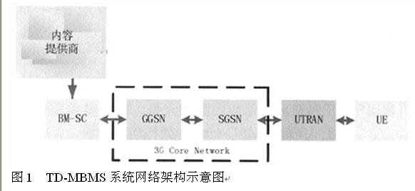
In the TD-SCDMA system, MBMS is based on 3GPP based on the GSM/GPRS core network evolution TD-SCDMA packet network, adding a new functional entity, the overall architecture of the MBMS network [3] is shown in Figure 1. In order to support the MBMS service, the network nodes in the original UMTS network, including the Gateway GPRS Support Node (GGSN), the Serving GPRS Support Node (SGSN), the Radio Network Controller (RNC), and the User Equipment (UE) have been updated. The content provider provides the content, and the transport stream is forwarded to the 3G core network through the broadcast service center BM-SC, forwarded to the UTRAN through the Iu, and sent to the UE through the Uu air interface.
The GGSN is the entry point for the MBMS service to enter the UMTS core network, and the GGSN transmits the MBMS content to the SGSN of the required MBMS service. The SGSN performs the associated MBMS Bearer Service control function. It is responsible for correctly transmitting packets to the user's network and supporting mobile performance management of the SGSN, enabling the RNC to efficiently utilize radio resources to transmit it to the terminal and support RNC mobility management. The BM-SC Broadcast Multicast-Service Center (BM-SC) is a new network node that serves as a content provider for the multicast service and serves as a network entry point for external MBMS data sources.
3. Introduction of the added MBMS function module of the MAC layer
To implement MBMS, 3GPP adds a functional entity MAC-m to implement the transmission of the user plane and control plane of the MBMS. Figure 2 illustrates the architecture and functional modules of MACRAN that add MAC-m to MAC-c/sh/m based on the original MAC-c/sh. As can be seen from the figure, in order to implement the MBMS function, the enhanced MAC-c/sh/m includes the following modules.
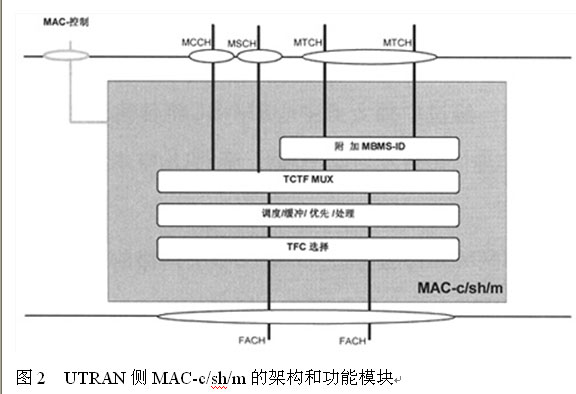
Figure 2 Architecture and function modules of MAC-c/sh/m on the UTRAN side
Scheduling/buffering/priority processing: for managing common transmission resources of MBMS and non-MBMS according to high-level requirements; TCTF MUX: inserting TCTF domain in MAC header, processing mapping between logical channel and transport channel; attaching MBMS - ID: For the Ptm type logical channel, the MBMS-ID field is added to the MAC header to distinguish different MBMS services; TFC selection: Select Transport Format Combination (TFC) for the Common Transport Channel (FACH).
On the UE side, the structure of the UTRAN is relatively modified, and the corresponding increase is made. FIG. 3 is a functional structure corresponding to the MAC layer of the UE side.
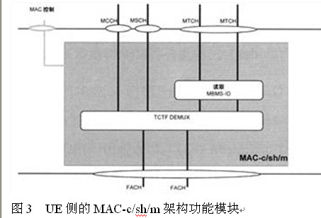
Figure 3 MAC-c/sh/m architecture function module on the UE side
TCTF DEMUX: Detects and deletes the TCTF field in the MAC header, handles the mapping between logical channels and transport channels; MBMS-ID reads: identifies specific MBMS services.
For the MBMS application, the UTRAN side notification indication channel (MICH), for each MBMS UE, sends a broadcast paging indication to inform the UE to receive the MBMS data transmitted by the UTRAN. Based on the information, the UE can obtain the MBMS information carried by the MTCH from the SCCPCH. The configuration information of the logical channel (MCCH) is added to the SIB5/Sbis of the BCCH. The UE can obtain the information about the MBMS by reading the configuration information. The MSCH is used to send the scheduling information of the MTCH. The MCCH and the MSCH are mapped to the FACH and the SCCPCH. The MTCH is used to transmit MBMS information. The MAC header is added to the MBMS-ID to distinguish different MBMSs and mapped into a specific FACH. The FACH is remapped to the SCCPCH and sent to the air interface.
4. "HSDPA+TD-MBMS" technology evolution
At present, TD-MBMS is implemented by means of a common channel, and the radio resource application of the air interface is still based on the technical mode of the traditional common channel, and the resource utilization rate is low. According to the evolution of the TD-SCDMA system and the MBMS improvement of the R6/R7, the MBMS technology based on HSDPA/MC-HSDPA/HSPA+ can be considered. Since HSDPA technology adopts fast scheduling, high-order modulation, fast link adaptive coding, and fast hybrid automatic repeat request, the system capacity is almost twice that of data services normally carried by DCH and DPCH, which greatly improves the utilization of wireless resources. Rate, use it to carry MBMS, can reduce the code channel resources required by MBMS, and greatly improve the utilization of air interface.
In 3GPP, in the partial MAC layer part of the UTRAN and the terminal side supporting MBMS and HSDPA, the MAC-hs entity is used to perform the function of HSDPA, and the HS-PDSCH and the HS-DSCH are defined to carry user data by MAC-c/sh. Configure the MAC-hs. After the cell is established, the NBAP signaling physically shares the link reconfiguration. After the HSDPA resource configuration is complete, the UE can use the HSDPA service. On the basis of implementing HSDPA, the interface between MAC-m and MAC-hs can be modified on the UTRAN side and the UE side respectively to transmit MBMS configuration information, control information and data information, and notify the MAC-configuration of the MBMS configuration. Hs; the content of the MSCH and the MTCH is sent to the MAC-hs through the interface between the MAC-m and the MAC-hs, and the module for processing the MSCH and the MTCH is added in the MAC-hs, and the MAC-hs adopts the HSDPA The scheduling mode implements the configuration of the control plane of the MBMS service and the bearer of the user plane. According to this structure, the function support of the HMSPA bearer-based MBMS can be implemented by modifying the MAC architecture for the UTRAN and the UE respectively. In MAC-hs, the HS-SCCH is used for information transmission of MBMS service information and MTCH-related time definition. The MBMS service data is handled by the HS-PDSCH. The improved mapping relationship of the channel is as shown in Figure 4, and the detailed functional module is improved. The information scheduling and transmission process is not given in this paper.
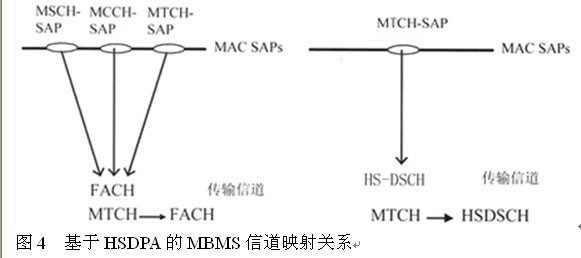
Figure 4 HMSPA-based MBMS channel mapping
5. E-MBMS evolved to LTE
The TD-MBMS system has followed the 3GPP standard technology to the greatest extent, laying a good foundation for the evolution of MBMS in the LTE system. LTE (Long Term Evolvement) is an evolution standard for 3GPP to develop 3G networks. In LTE, MBMS is called Enhanced MBMS (E-MBMS). E-MBMS is a low-cost evolution from Release 6, supporting enhanced broadcasts. Broadcast business. A mobile TV system is deployed on a separate downlink carrier, supporting enhanced IMS (IP Multimedia Subsystem) and core network. E-MBMS can support the transmission of higher-speed multimedia data to provide better quality of service. Since LTE greatly improves the transmission capability of the physical layer, and in order to reduce the complexity of the system, E-MBMS technology has more existing broadcasts. Some improvements have been made based on the broadcast technology. Its architecture is shown in Figure 5.
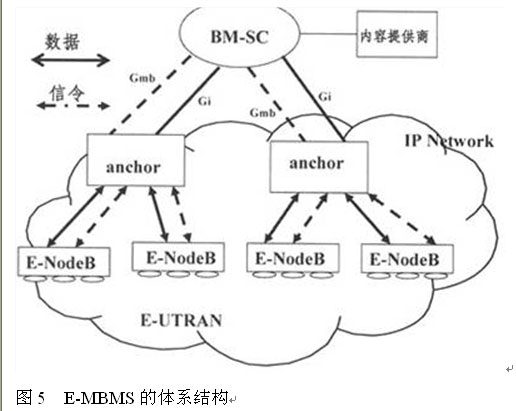
Figure 5 E-MBMS architecture
E-UTRAN discards the RNC-Node B structure of UTRAN, the RNC node is cancelled, and the node called Anchor is replaced. The RLC sublayer is cancelled in the Anchor node, and the retransmission function of the RLC sublayer is placed in the MAC sub-interface. Layer, this function is called Oute-ARQ to distinguish HARQ. Secondly, the E-MBMS technology cancels the SGSN and GGSN nodes, the Gmb and Gi interfaces terminate at the E-Node B, and the BM-SC directly interacts with the Anchor.
The Broadcast Multicast (MBMS) system can be multiplexed with the unicast system, or can be deployed on a single carrier, which is divided into single-cell MBMS and multi-cell MBMS deployment scenarios. Multi-cell merging requires inter-cell synchronization and common reference signals. The single-cell MBMS needs the cell-specific reference signal to optimize the MBMS parameters. Since the radius of the MBMS cell is much larger than that of the ordinary cell and the multi-cell combination is required, the CP length needs to be increased, so that the sub-carrier width can be reduced to avoid the spectrum efficiency. . At the same time, since MBMS is mainly used for low-speed mobility, a smaller subcarrier spacing can be used, the MBMS subcarrier spacing is 7.5 kHz, and the CP length is increased to 33.33 us.
Since in LTE, compared with UTRAN, E-UTRAN has greatly simplified the channel structure, the transmission channel will be reduced from the original 9 to 5, and the logical channel will be reduced from the original 10 to 7. In E-MBMS, the MCH only provides data bearers for multi-cell broadcast/multicast services, while the broadcast/multicast service data for single cells is carried on the SCH channel. The MBMS transmits the MBMS service through the secondary common control physical channel or the dedicated physical downlink channel, and the E-MBMS transmits the MBMS service through the high-speed physical downlink shared channel. Since the high-speed physical downlink shared channel supports the broadcast function of the whole cell, in the E-MBMS There is no radio bearer for PTP. At the same time, the layered modulation technology is adopted in E-MBMS, that is, different modulation modes are adopted for different parts of the MBMS service.
6, the conclusion
This paper introduces and analyzes the technology and development based on TD-MBMS. TD-MBMS is based on the modification and upgrade of the original TD-SCDMA network, especially the terminal, which inherits the existing 3GPP standard to the maximum extent. In particular, LTE-based E-MBMS will meet the growing demand for mobile data services, and will certainly be a key technology for the next generation of mobile communication technologies such as Wimax.
Wire Feeding Roller is part of the spraying system.
Wire Feeding Roller
Wire Feeding Roller,Welding Wire Feed Roller,Wire Feeder Roller,Wire Feed Drive Roller
Shaoxing Tianlong Tin Materials Co.,Ltd. , https://www.tianlongspray.com