
Ambient light sensor (ALS) backlight control solution
introduction
Ambient light sensor (ALS) integrated circuits are increasingly used in various displays and lighting equipment to save power and improve the user experience. With the ALS solution, the system designer can automatically adjust the brightness of the display according to the ambient light intensity. Because the power consumption of backlight lighting occupies a large proportion of the total power consumption of the system, implementing dynamic backlight brightness control can save a lot of power. In addition, it can improve the user experience, allowing the brightness of the display to adjust itself to the best state according to the ambient light conditions.
Three parts are needed for system implementation: light sensors to monitor ambient light intensity, data processing devices (usually microcontrollers), and actuators that control the backlight input current.
Backlight control: ambient light sensor
FIG. 1 is an exemplary block diagram of a system implementing backlight control. In this combination, the light sensor is a key component because it provides ambient light intensity information to other modules of the system. The light sensor must have a signal converter (such as a photodiode or CdS photoresistor), a signal amplification and / or adjustment device, and an analog-to-digital converter (ADC) that convert the optical signal into an electrical signal.
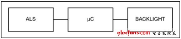
Figure 1. Block diagram of a system implementing backlight control
Figure 2 shows a discrete photodiode circuit. It can be seen from the figure that the circuit requires one or more operational amplifiers: one for the conversion of current to voltage, and may also require a first-stage amplification to provide additional gain. It also includes some branch circuits for power supply to ensure a highly reliable signal chain. In applications where space is extremely valuable, too many components may cause space constraints.
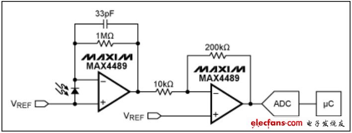
Figure 2. Discrete design of photodiode circuit
There is a more subtle problem here. Specifically, ideally, it should be ensured that the measurement of ambient light mimics the response mechanism of the human eye to light. This is usually aided by the visual brightness curve provided by CIE (Figure 3). However, photodiodes are rarely able to fully simulate this response mechanism, because they usually have a high infrared (IR) sensitivity. Under light conditions with high IR intensity (such as incandescent lamps or daylight), this infrared sensitivity can cause incorrect judgment of light intensity.
One way to solve the above problem is to use two photodiodes: one uses components sensitive to both visible and infrared light, and the other uses components sensitive only to infrared light. Finally, the former's response value is subtracted from the latter's response value to minimize infrared interference and obtain an accurate visible light response.
Although this solution is effective, it increases the footprint of the discrete circuit. It is often difficult, if not impossible, to match two discrete photodiodes tightly enough to eliminate infrared interference. Without precision amplifiers (such as logarithmic amplifiers), the dynamic range may be small. In other words, it is difficult to use this combination to obtain repeatable results.
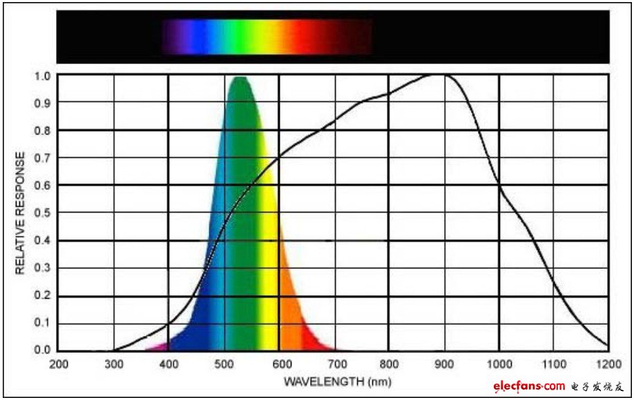
Figure 3. CIE curve and typical photodiode
Wind Turbine For Home, Connect Wind Turbine to Grid Tie Inverter , Off Grid Wind Turbine Kit, Residential Wind Turbine, Small Wind Turbine, 3 Phase Wind Turbine
Wind Turbine, Horizontal Axis Wind Turbine, Permanent Magnet Wind Turbine, PMG Wind TurbinePMG Horizontal Axis Wind Turbine
Wind Turbine, Horizontal Axis Wind Turbine, Permanent Magnet Wind Turbine, PMG Wind Turbine
Delight Eco Energy Supplies Co., Ltd. , https://www.cndelight.com