
Design of EMI compatible automotive switching regulator
You can easily design EMI-compatible automotive switching regulators without fully understanding complex EMI. This article will discuss the basic factors for the successful implementation of switching regulators in an intuitive way without complicated mathematical operations, including: slew rate control, filter design, component selection, configuration, noise diffusion, and shielding.
The car itself is constantly changing, as are the electronic devices that drive the car. One of the most notable is the plug-in electric vehicle (PEV), which replaces the gas tank and the internal combustion engine with 300V to 400V lithium ion batteries and three-phase propulsion motors. Sophisticated battery pack power monitoring, regenerative braking system and complex transmission control can optimize the battery usage time, making the battery need to be charged less frequently. In addition, today's electric cars or other types of cars have many electronic modules that can improve performance, safety, convenience, and comfort. Many mid-range cars are equipped with advanced global positioning system (GPS), integrated DVD player and high-performance audio system.
Accompanying these advanced equipments is the demand for higher processing speeds. Therefore, today's automobiles integrate high-performance microprocessors and DSPs, which lower the core voltage to 1V and increase the current by 5A. Making automotive batteries between 6V and 40V produce such voltages and currents requires many difficulties, one of which is to meet the strict standards of electromagnetic compatibility testing (EMC). Linear regulators used to be the main method used to convert car battery voltages to regulated power supply voltages, but they are now out of date. More precisely, a linear regulator reduces the output voltage and increases the load current. Switching regulators are becoming more and more widely used, and with it comes concerns about electromagnetic interference (EMI) radio frequency and the emphasis on safety systems.
Implement EMC of switching power supply with simple method
The purpose of this article is to try to design an EMI-compatible switching regulator without fully understanding complex EMI. In fact, all problems related to EMI stem from the fact that the rate of voltage and current changes in the switching regulator is not fully achieved, and the interaction with parasitic circuit components on the signal lines of the circuit board or within the components. Take the example of a 200kHz step-down switching regulator powered by a car battery rated at 14V and 5A to produce 5V. To achieve considerable efficiency, the voltage slope of the switch node should only account for a short period of the on-time, for example Below 1/12. The on-time of a buck converter operating in continuous conduction mode (CCM) is D / fsw, where D is the ratio of the duty cycle or pulse width modulation (PWM) signal turn-on time percentage to the entire time (ton and toff), and fsw is the switching frequency of the converter.
For a buck converter operating in CCM, the inductor current is always a non-zero positive current. In this case, the duty cycle is D = Vout / Vin, in this case 38% (5V / 14V). Using a switching frequency of 200kHz, we quickly calculated the on-time of 1.8μs. To support this frequency, the rise / fall time of the control switch must be less than 90 nanoseconds. This makes us notice the first noise reduction method, namely slope control. You may not understand it, but at this time we are very aware of the harmonics related to the PWM switching node, that is, the control waveform of the switching regulator. If this waveform is represented by the trapezoid shown in Figure 1 (a), the harmonics of the waveform can be represented by the content in Figure 1 (b), which indicates the driving factor behind EMI. This Fourier envelope defines the harmonic amplitude that can be obtained by Fourier analysis or calculation of trapezoidal waveform conduction time and rise time.
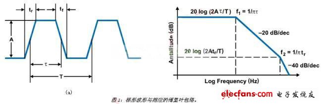
When observing the frequency domain, it can be seen that the trapezoidal waveforms with equal rise and fall times are composed of different harmonic signals, which exist in integer multiples of the fundamental frequency of the periodic signal. It is worth noting that the energy of each harmonic will be reduced to 20dB / dec at the first turning point (on time) of 1 / (Ï€ & TImes; Ï„), and reduced at the second turning point of 1 / (Ï€ & TImes; tr) To 40dB / dec. Therefore, limiting the slope of the switch node waveform has a significant impact on reducing the amount of transmission. Through this discussion, it should be able to clearly show that reducing the operating frequency is also conducive to reducing the amount of emissions.
AM radio frequency band considerations
One of the difficulties in automotive EMI specifications is related to the AM frequency band. This frequency band starts from 500kHz and continues to 2MHz, which is very suitable for switching regulators. Since the highest energy component of the trapezoidal waveform is the basic component (assuming that there is no circuit board resonance), it can operate up and down the AM band.
Does the duty cycle matter?
Another important factor is that if the duty cycle is exactly 50%, all the energy of the complex trapezoidal switching waveform will appear as odd harmonics (1, 3, 5, 7 ...). Therefore, operating at 50% duty cycle is the worst case. At load cycles around 50%, even if harmonics occur, natural EMI diffusion will occur.
EMI and EMC standards
You can think of EMI as unsuitable energy, and this energy may violate the emission standards without too much. In fact, EMI is a fairly low energy effect. For example, under the condition of 1MHz, as long as the EMI of 20nW will violate the FCC regulations on conducted emissions. Conducted emission is measured by a spectrum analyzer monitoring the high-frequency components of the input source. The Line Impedance Stabilization Network (LISN) can be used as a low-impedance switching regulator and as a high-pass filter for spectrum analyzer line noise. Therefore, the input of the switching regulator is the next thing to pay attention to.
9gram Tealight Candle burning time 2 hours
10gram tealight candle burning time 2.5 hours
11gram tealight candle burning time 3 hours
12Gram Tealight Candle burning time 3.5 hours
13gram tealight candle burning time 3.5-4 hours
14Gram Tealight Candle burning time 4-4.5 hours
white unscented tealight candle made of 100% paraffin wax . 100pcsx10bag/ctn 50pcsx20bag/ctn this is popular packing way ,polybag or box .
shipment is very quickly ,and after 30days when get the depsoit .
Tealight Candle
Tealight Candle,White Tealight Candles,Pillar Tealight Candle,Mini Tealight Candle
Shijiazhuang Zhongya Candle Co,. Ltd. , https://www.zycandlefactory.com