
Stm32 timer input capture
The system tick timer is generally used to provide a "heartbeat" effect, while the most basic function of the STM32 timer is also timing, and timing can be set for different time lengths. In addition to the most basic timing functions, the timer is hooked to the GPIO so that it can play a powerful role. For example, it can output square wave signals and PWM signals with different frequencies and different duty cycles, and at the same time, as an input capture function. Pulse width measurement, capacitive button detection, etc. can be measured.
First, the input capture conceptThe input capture mode can be used to measure the pulse width or the measurement frequency. STM32 timers, in addition to TIM6 and TIM7, have other input capture functions. The input capture of the STM32, simply by detecting the edge signal on TIMx_CHx (channel X of timer X), will change the value of the current timer (TIMx_CNT) when the edge signal transitions (such as rising/falling edges). ) Store in the capture/compare register (TIMx_CCRx) of the corresponding channel to complete a capture. It is also possible to configure whether to trigger interrupt/DMA, etc. during capture.
This article uses TIM2_CH1 to capture the high-level pulse width, that is, to set the input capture to the rising edge detection and record the value of TIM2_CNT when the rising edge occurs. The capture signal is then configured to capture on the falling edge. When the falling edge comes, the capture occurs and the TIM2_CNT value at this time is recorded. Thus, the difference between TIM2_CNT and TMB2_CNT is the pulse width of the high level, and the counting frequency of TIM2 is known, so that the accurate time of the high pulse width can be calculated.
As for why TIM2_CH1 measures the pulse width of WK_UP. . Look at the picture:
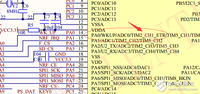
Obviously, TIM_CH1 is connected to PA0.
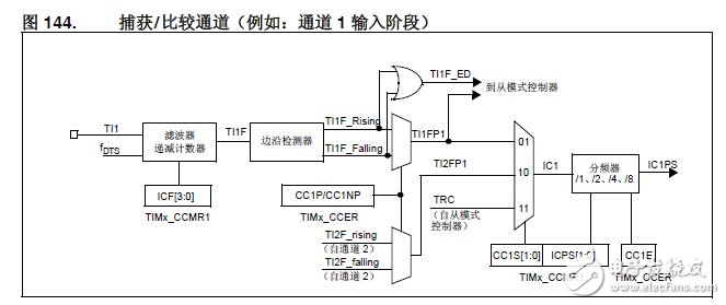
Second, the input capture process:For example, to configure the up counter to count on the rising edge of the T12 input, use the following steps:
1. Configure TIMx_CCMR1 register CC2S='01', configure channel 2 to detect the rising edge of TI2 input.
2. Configure IC2F[3:0] in the TIMx_CCMR1 register to select the input filter bandwidth (if no filter is required, keep IC2F=0000 without filter, sample with fDTS)
3. Configure CC2P='0' in the TIMx_CCER register to select the rising edge polarity.
4. Configure SMS='111' in the TIMx_SMCR register to select the timer external clock mode.
5. Configure TS='110' in the TIMx_SMCR register and select TI2 as the trigger input.
6. Set the CEN='1' of the TIMx_CR1 register to start the counter.
When the rising edge appears at TI2, the counter counts once and the TIF flag is set. The delay between the rising edge of TI2 and the actual clock of the counter depends on the resynchronization circuit at the TI2 input.
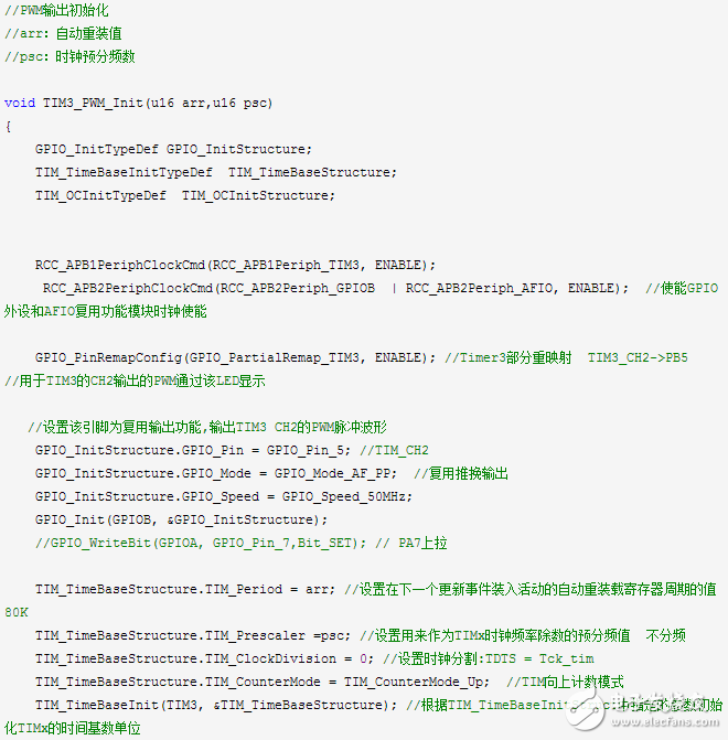
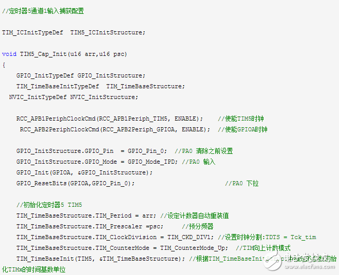
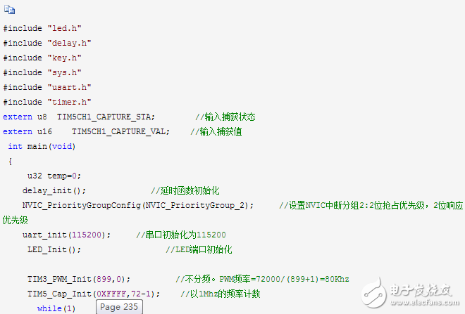
1) Turn on the TIM5 clock and GPIOA clock, and configure PA0 as the pull-down input.
To use TIM5, we must first turn on the TIM5's clock. Here we also need to configure PA0 as the pull-down input because we want to capture the high pulse width above TIM5_CH1, and TIM5_CH1 is connected above PA0. So to do GPIO_Init();
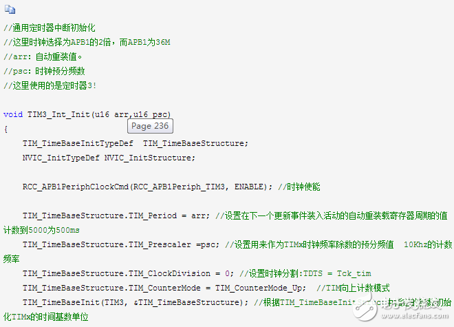
2) Initialize TIM5 and set the ARR and PSC of TIM5.
After turning on the TIM5 clock, we set the values ​​of the two ARR and PSC registers to set the auto-reload value and count frequency of the input capture. This is done in the library function via the TIM_TimeBaseInit function.
TIM_TimeBaseInitTypeDef TIM_TimeBaseStructure;
TIM_TimeBaseStructure.TIM_Period = arr; //Set counter auto reload value
TIM_TimeBaseStructure.TIM_Prescaler =psc; //Set the prescaler value
TIM_TimeBaseStructure.TIM_ClockDivision = TIM_CKD_DIV1; //TDTS = Tck_tim
TIM_TimeBaseStructure.TIM_CounterMode = TIM_CounterMode_Up;//TIM count up mode
TIM_TimeBaseInit(TIM5, &TIM_TimeBaseStructure); //Initialize Tim5 based on the specified parameters
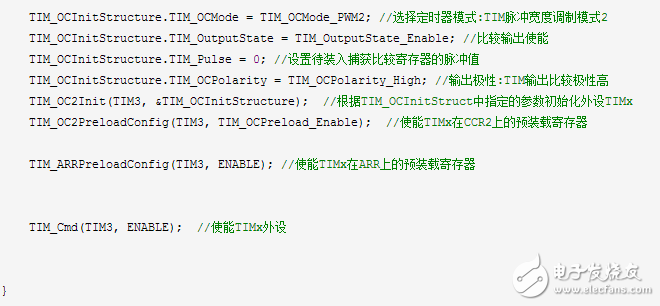
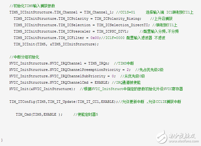
3) Set the input comparison parameters of TIM5 and enable input capture.
The settings of the input comparison parameters include mapping relationship, filtering, frequency division, and capture mode. Here we need to set channel 1 to input mode, and IC1 maps to TI1 (channel 1), and does not use filtering (increasing response speed), rising edge capture. The library function initializes the input comparison parameters with the TIM_ICInit function:
Void TIM_ICInit(TIM_TypeDef* TIMx, TIM_ICInitTypeDef* TIM_ICInitStruct);
Again, let's take a look at the definition of the parameter setting structure TIM_ICInitTypeDef:
Typedef struct
{
Uint16_t TIM_Channel; / / used to set the channel
Uint16_t TIM_ICPolarity; / / used to set the effective capture polarity of the input signal
Uint16_t TIM_ICSelection; //
Uint16_t TIM_ICPrescaler;
Uint16_t TIM_ICFilter;
} TIM_ICInitTypeDef;
The parameter TIM_Channel is well understood and is used to set the channel. We set it to channel 1, which is TIM_Channel_1.
The parameter TIM_ICPolarit is used to set the effective capture polarity of the input signal, here we set TIM_ICPolarity_Rising, the rising edge capture.
At the same time, the library function also provides a separate function to set the channel 1 capture polarity:
TIM_OC1PolarityConfig(TIM5, TIM_ICPolarity_Falling);
This means that channel 1 is captured on the rising edge. We will use it later. There is also a similar function for the other three channels. When using it, be sure to know which channel to use which function to call. The format is TIM_OCxPolarityConfig(). The parameter TIM_ICSelection is used to set the mapping relationship. We configure IC1 to map directly on TI1 and select TIM_ICSelection_DirectTI.
The parameter TIM_ICPrescaler is used to set the input capture frequency division coefficient. We do not divide the frequency here, so select TIM_ICPSC_DIV1, and there are 2, 4, and 8 frequency division options.
The parameter TIM_ICFilter sets the filter length. We do not use a filter here, so it is set to 0. The configuration code is:
TIM_ICInitTypeDef TIM5_ICInitStructure;
TIM5_ICInitStructure.TIM_Channel = TIM_Channel_1; //Select input IC1 to map to
TIM5_ICInitStructure.TIM_ICPolarity = TIM_ICPolarity_Rising on TI1; // rising edge capture
TIM5_ICInitStructure.TIM_ICSelection = TIM_ICSelection_DirectTI; //map to
TIM5_ICInitStructure.TIM_ICPrescaler = TIM_ICPSC_DIV1 on TI1; //Configure input crossover, no crossover
TIM5_ICInitStructure.TIM_ICFilter = 0x00;//IC1F=0000 Configure the input filter to not filter
TIM_ICInit(TIM5, &TIM5_ICInitStructure);
4) Enable capture and update interrupts (set the DIER register of TIM5)
Because we want to capture the pulse width of the high level signal, the first capture is the rising edge, the second capture is the falling edge, and after the rising edge is captured, the capture edge is set to the falling edge, and if the pulse The width is longer, then the timer is
Will overflow, must deal with the overflow, otherwise the result will not be allowed. These two things, we are all doing it in the interruption, so we must
Turn on capture interrupts and update interrupts.
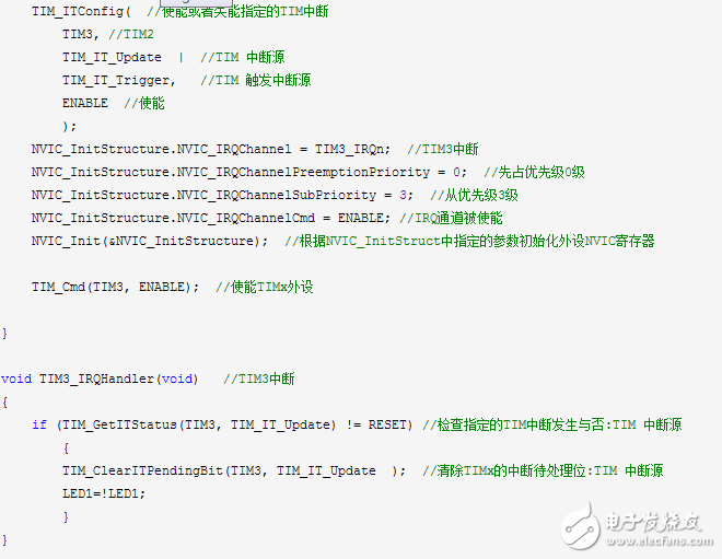
Here we use the timer's open interrupt function TIM_ITConfig to enable capture and update interrupts: Allow update interrupts and capture interrupts
TIM_ITConfig(TIM5, TIM_IT_Update|TIM_IT_CC1, ENABLE);
5) Set interrupt grouping, write interrupt service function
The method of setting the interrupt grouping is not explained, mainly through the function NVIC_Init(). After the grouping is completed, we also need to complete key operations such as data processing and capture settings in the interrupt function to achieve high-level pulse width statistics. In the interrupt service function, as in the previous external interrupt and timer interrupt experiments, we need to judge the interrupt type at the beginning of the interrupt, and clear the interrupt flag at the end of the interrupt. The functions used have been explained in the above experiments, namely the TIM_GetITStatus() function and the TIM_ClearITPendingBit() function.
6) Enable timer (set the CR1 register of TIM5)
Finally, the counter switch of the timer must be turned on, the counter of the TIM5 is started, and the input capture is started. Enable the timer 6 step setting, channel 1 of timer 5 can start input capture.
TIM_Cmd (TIM5, ENABLE);
The hardware resources used in this experiment are:
1) Indicator light DS0
2) WK_UP button
3) Serial port
4) Timer TIM3
5) Timer TIM5
We will capture the high pulse width on TIM5_CH1 (PA0), input the high level through the WK_UP button, and print the high pulse width from the serial port. At the same time, we reserve the PWM output of the previous section and measure the high pulse width of the PWM output by connecting PB5 and PA0 with DuPont line.
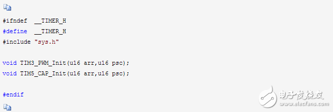
Timer.h file:
Timer.c file:
Main.c file:
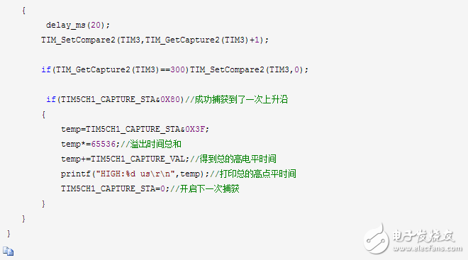
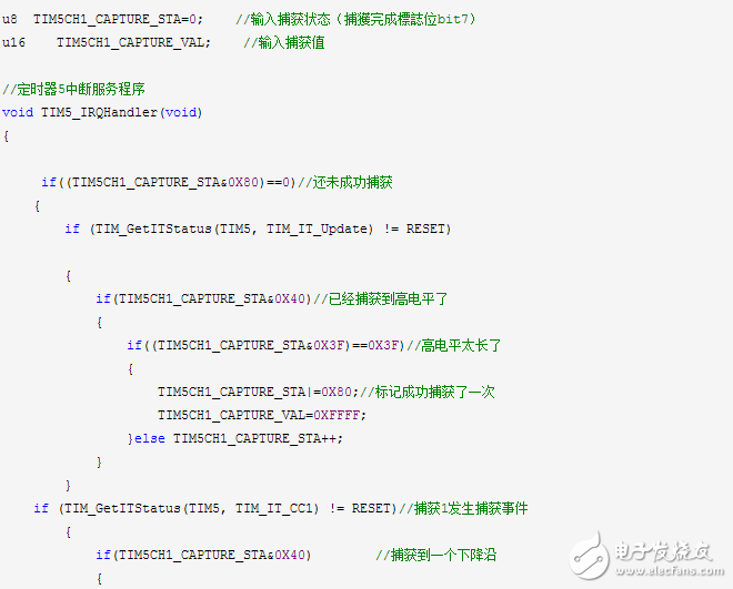
TIM5_IRQHandler is the interrupt service function of TIM5, which uses two global variables to assist in high-level capture. TIM5CH1_CAPTURE_STA is used to record the capture state. This variable is similar to the USART_RX_STA register we defined in usart.c (actually a variable, but we use it as a register). The other variable, TIM5CH1_CAPTURE_VAL, is used to record the value of TIM5_CNT when the falling edge is captured.
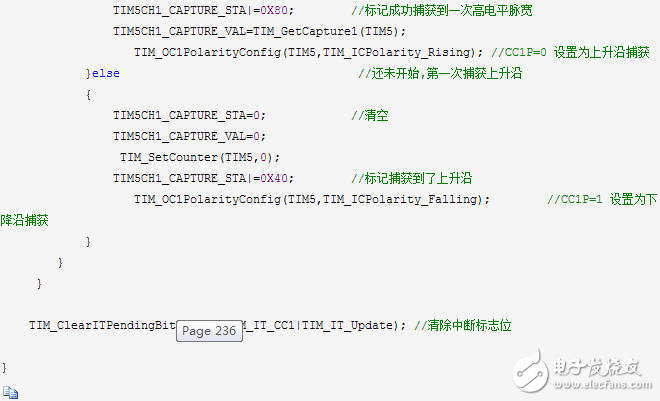
Now let's introduce the idea of ​​capturing a high pulse width: first, set TIM5_CH1 to capture the rising edge, which is set when the TIM5_Cap_Init function is executed, and then wait for the rising edge interrupt to arrive. When the rising edge interrupt is captured, this If the 6th bit of TIM5CH1_CAPTURE_STA is 0, it means that the new rising edge has not been captured, first clear TIM5CH1_CAPTURE_STA, TIM5CH1_CAPTURE_VAL and TIM5-"CNT, etc., then set the 6th bit of TIM5CH1_CAPTURE_STA to 1, the tag is captured. High level, finally set to capture on the falling edge, waiting for the falling edge to arrive. If the timer overflows while waiting for the falling edge, the number of overflows is counted in TIM5CH1_CAPTURE_STA. When the maximum number of overflows comes, the flag capture is completed (although the falling edge has not been captured yet). When the falling edge comes, first set the 7th bit of TIM5CH1_CAPTURE_STA to 1, the flag captures a high level successfully, then reads the timer value at this time into TIM5CH1_CAPTURE_VAL, and finally sets it to the rising edge capture and returns to the initial state. In this way, we complete a high-level capture. As long as the 7th bit of TIM5CH1_CAPTURE_STA is always 1, then the second capture will not be performed. After the main function has processed the captured data, set TIM5CH1_CAPTURE_STA to zero to start. The second capture.
Download the program, connect the window, set the baud rate to 9600. When the PA0 pulse signal is given, the pulse width can be displayed through the serial port. At the same time, PB5 can be connected to PA0, that is, the PWM width of the output can be tested.
Shaft inserting is one of the process for rotor production for motors and generators. Some of customers require the Rotor Core, but some of them also require the rotor with shaft. We are able to do shaft inserting for both samll and big rotors. And we can also do lathe work for rotors after inserting the shafts.
Rotor Shaft Inserting,Rotor Shaft,Rotor With Shaft,Motor Rotor Shaft
Henan Yongrong Power Technology Co., Ltd , https://www.hnyongrongglobal.com