
Application of PWM Signal in LED Driver Power Supply
Pulse Width Modulation (PWM) is a very effective technique for controlling analog circuits using the digital output of a microprocessor. It is widely used in many fields from measurement and communication to power control and conversion, with simple and flexible control. And the advantages of dynamic response and become the most common control method of power electronics technology.
First, the principle of PWMThe pulse width modulation (PWM) control method is to control the on/off of the switching device of the inverter circuit, so that the output end obtains a series of pulses of equal amplitude, and these pulses are used instead of the sine wave or the required waveform. That is, a plurality of pulses are generated in a half cycle of the output waveform so that the equivalent voltage of each pulse is a sinusoidal waveform, and the obtained output is smooth and the low harmonics are small. By modulating the width of each pulse according to a certain rule, the output voltage of the inverter circuit can be changed, and the output frequency can also be changed. As shown in FIG. 1, the pulse width modulation principle diagram is shown.
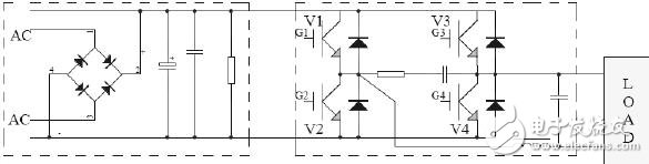
Figure 1 Pulse width modulation schematic
For example, by dividing the sinusoidal half-wave waveform into N equal parts, the sinusoidal half-wave can be regarded as a waveform composed of N pulses connected to each other. If the above pulse sequence is replaced by the same number of rectangular pulse sequences of equal width and not equal width, the midpoint of the rectangular pulse coincides with the midpoint of the corresponding sinusoidal equal division, and the rectangular pulse and the corresponding sinusoidal partial area (ie, impulse) are made. Equal, you get a set of pulse sequences, this is the PWM waveform. According to the principle that the impulse equal effect is the same, the PWM waveform and the sine half wave are equivalent, as shown in FIG. 2 is a sine wave PWM modulation waveform.
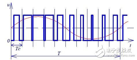
Figure 2 sine wave PWM modulation
Second, the role of PWM in LED drive powerThe PWM signal drive is one of the LED drive power supplies. Many LED applications require dimming, such as LED backlighting or architectural lighting dimming. The dimming function can be achieved by adjusting the brightness and contrast of the LEDs. Simply reducing the current in the device may allow adjustment of the LED illumination, but having the LED operate below the rated current can have many undesirable consequences, such as chromatic aberration. A replacement for simple current regulation is to integrate a pulse width modulation (PWM) controller in the LED driver.
The PWM signal is not used directly to control the LED, but rather controls a switch, such as a MOSFET, to provide the required current to the LED. The PWM controller typically operates at a fixed frequency and adjusts the pulse width to match the desired duty cycle. The application's system simply needs to provide wide and narrow digital pulses to simply change the output current. To adjust the brightness of the LED. Most current LED chips use PWM to control LED illumination. To ensure that people do not notice significant flicker, the frequency of the PWM pulse must be greater than 100 Hz. The main advantage of PWM control is that the dimming current through PWM is more accurate, and the chromatic aberration when the LED is illuminated is minimized. As shown in Fig. 3, the pulse width modulation (PWM) LED driver control circuit is shown.
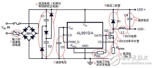
Figure 3 Pulse Width Modulation (PWM) LED Driver Control Circuit
Third, how to accurately analyze the PWM signal in the LED driver power supplyThe role of the PWM signal in the LED driver power supply is self-evident, so how can we make a high-quality PWM driver power supply? Based on the 512M memory depth, Guangzhou Zhiyuan Electronics ZDS4054PLUS oscilloscope can observe the change of pulse width length when the PWM driver controls LED light changes for a long time, which is convenient for engineers to accurately adjust the brightness of the light. The waveform refresh rate of 1 million times per second and the rich trigger mode quickly capture the PWM signal, and in the ZOOM amplification mode, the waveform details can be analyzed. Figure 4 shows the PWM signal modulation waveform.

Figure 4 PWM modulation signal
At the same time, the most important thing in the LED driver power supply is to accurately measure the pulse width signal. The ZDS4054PLUS oscilloscope can accurately measure the parameters such as pulse width, amplitude and signal rise time based on 51 parameter measurements, greatly speeding up the research and development process. The PWM waveforms that are triggered each time are stored by the segmentation storage method for analysis. Figure 5 shows the PWM signal amplification waveform measured using the ZDS4054Plus oscilloscope.
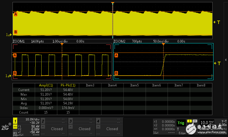
Figure 5 PWM signal ZOOM amplified waveform
Lithium Batteries 72V,Lithium Batteries 200A Rechargeable,Customized Rechargeable Lithium Battery,Lithium Ion Battery
Shaoxing Honyo International Trading Co., Ltd , https://www.honyopower.com