
Circuit principle and basic structure of phase-locked loop PLL
A phase locked loop, as the name implies, is a loop that locks the phase. Anyone who has learned the principle of automatic control knows that this is a typical feedback control circuit that uses the externally input reference signal to control the frequency and phase of the internal oscillating signal of the loop to achieve automatic tracking of the input signal frequency to the input signal frequency. Used for closed loop tracking circuits. It is a method for making the frequency more stable in radio transmission, mainly including VCO (Voltage Controlled Oscillator) and PLL IC (Phase Locked Loop Integrated Circuit). The voltage controlled oscillator gives a signal, one part is output and the other part is divided. The frequency is compared with the local oscillator signal generated by the PLL IC. In order to keep the frequency constant, the phase difference is not changed. If there is a phase difference, the voltage at the voltage output of the PLL IC changes to control the VCO. Until the phase difference is restored, the purpose of phase locking is achieved. A closed loop electronic circuit that maintains a determined relationship between the frequency and phase of the controlled oscillator and the input signal.
PLL (phase-locked loop) circuit principle
In an oscillating circuit used in a communication device or the like, the required frequency range is wide, and the frequency stability is high. No matter how good the LC oscillator circuit is, its frequency stability cannot be compared with the crystal oscillator circuit. However, the crystal oscillator can hardly change its frequency except that it can be divided by a digital circuit. If a PLL (Phase Locked Loop) (Phase Locked Loop) technology is used, the stability of the frequency is high except for a wide range of oscillation frequencies. This technique is commonly used in radios, on the tuning circuitry of televisions, and on circuits on CD players.
Basic structure of PLL (phase locked loop) circuit
Summary of PLL (Phase Locked Loop) Circuit
Figure 1 shows the basic block diagram of a PLL (Phase Locked Loop) circuit. The reference signal used here is a highly stable crystal oscillator circuit signal.
The center of this circuit is the phase comparator. The phase comparator can compare the reference signal with the phase of the VCO (Voltage Controlled Oscillator). If there is a phase difference between the two signals, a phase error signal output is generated.
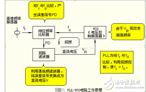
(Comparing the oscillation frequency of the VCO with the reference frequency, using the control of the feedback circuit, the frequencies of the two are identical.)
With this error signal, the oscillation frequency of the VCO can be controlled such that the phase of the VCO coincides with the phase (ie, frequency) of the reference signal.
The PLL (Phase Locked Loop) allows the frequency of the high frequency oscillator to coincide with the frequency of an integer multiple of the reference frequency. Since the reference oscillator is mostly a crystal oscillator, the frequency stability of the high frequency oscillator can be compared with that of a crystal oscillator.
As long as it is an integral multiple of the reference frequency, the output of various frequencies can be obtained.
From the basic configuration of the PLL (phase locked loop) of Fig. 1, it can be known that it is composed of a VCO, a phase comparator, a reference frequency oscillator, and a loop filter. Here, it is assumed that the frequency of the reference oscillator is fr and the frequency of the VCO is fo.
In this circuit, it is assumed that fr "fo", that is, when the oscillation frequency fo of VC0 is lower than fr. At this time, the output PD of the phase comparator will generate a positive pulse signal as shown in FIG. 2, so that the oscillator frequency of the VCO is increased. Conversely, if fr "fo, a negative pulse signal is generated.
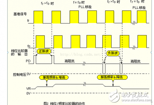
(This is a comparison of the two signals using the edge of the pulse. If there is a phase difference, a positive or negative pulse output will be produced.)
The PD pulse signal is integrated by a loop filter to obtain a DC voltage VR, which can control the VCO circuit.
Due to the change in the control voltage vr, the VCO oscillation frequency is increased. The result is fr=f. When the phases of f and f match, the PD pin becomes in a high impedance state, and the PLL (phase locked loop) is locked.
How the phase comparator works
The phase comparator described here is phase. A type of frequency comparator (PFC: Phase-Frequency Comparator), which is included in the LSIMC145163P described later.
This type of phase is not only a phase comparison, that is, it is not just a comparison. In the case where the frequency f is different, it can also be used as a frequency comparator.
The relationship between the phase difference Δ and the time t is
In the case where only phase detection is performed, for example, it may be impossible to discriminate whether it is a delay of 300° or a advance of 60°. However, in the phase-frequency comparator, if fr "fo" is regarded as the phase delay.
Loop filter selection method
glitter keychain,luminous keychains,glitter keychain molds,keychains bulk,keychain wholesale,shiny keychain
Shenzhen Konchang Electronic Technology Co.,Ltd , https://www.konchang.com