
Research and Development of Automotive Bus System
The research and development of automobile bus system can be divided into three stages: The first stage is to study the basic control system of the automobile (also known as the comfort bus system), such as lighting, electric windows, and central control lock. The second stage is to study the main control system (also known as power bus system) of the car, such as EFI ECU control system, ABS system, automatic transmission, etc. The third stage is to study the comprehensive, real-time control and information feedback between the various electronic control systems of automobiles.
According to China's automotive electronic technology development plan, after entering the 21st century, car electronic technology can reach the level of the 1990s abroad. In order to shorten the gap with the foreign car technology level and improve its own competitiveness, simply relying on technology introduction is not conducive to development, digestion, absorption, Research and development of their own automotive bus and network application system is in line. At present, China's automobile bus research and application is still in its infancy, and the application trend of automobile bus is obvious. Now it is a good time to intervene in this research. Welcome to reprint, this article comes from the electronic enthusiast network ().
Research focus of automotive bus
Since China's models are mainly European and American models, and CAN buses are the mainstream in European and American models, at present, almost all models using bus technology in China use CAN bus, so the research and development of automotive bus should be based on the actual situation at home and abroad.
CAN conforms to the reference model of ISO / OSI, but only specifies the protocols of the physical layer and the data link layer. The protocol of the application layer needs to be defined by the user. There are many chips that support the CAN low-level protocol, both on-chip MCUs and off-chip CAN controllers. There are many application layer protocols developed by users themselves. For example, the DEVICENET protocol defined by AB is the application layer protocol based on the CAN protocol. The SDS bus launched by Honeywell also defines its own application layer on the basis of CAN. It can be seen that the research focus of the automotive CAN bus is to develop ECU hardware and application layer software for specific vehicle models, and form an in-vehicle network.
Key technology
Using CAN bus to build an in-vehicle network, the key technical problems to be solved are:
1) Technical issues such as the rate, capacity, priority level, and node capacity of the information transmitted by the bus; 2) Reliable data transmission in a high electromagnetic interference environment; 3) Determining the maximum transmission delay; 4) Network fault tolerance technology; 5 ) Network monitoring and fault diagnosis function;
Bus network system overview
With the improvement of the performance of automotive electronic control systems, especially the improvement of controller chips and software performance, automotive bus network systems can not only share information and save wiring harnesses, but also provide richer software functions to enhance the value and competitiveness of products To meet the needs of automobile reliability and comfort. The bus technologies corresponding to these functions include:
Network management: The controller monitors the running status of the network through network management. Once a communication failure is found, it immediately takes failure treatment. The sleep and wake-up functions of the network management can coordinate the power management of each controller, thereby reducing the battery power consumption when the vehicle is parked.
Diagnosis: Diagnosis can not only read the fault code, but also realize two important functions of offline configuration and detection, and program download. Automated off-line configuration and detection functions can quickly and comprehensively configure and test the functions of the controller (such as window zero position configuration and anti-trap detection), thereby ensuring the quality of the car factory and speeding up the production line. Through the program download function, OEMs can refresh the controller software in the 4S shop, thereby reducing the recall cost caused by software defects.
Measurement and calibration: During the development of new models, the rapid control prototype controller using measurement and calibration technology can adjust the control parameters and algorithms in real time and conveniently through the computer and network system, which greatly reduces the development cycle and cost. This technology is commonly used in the development of new energy vehicles in Europe, the United States and Japan.
Foreign GM, Ford, Volkswagen, etc., as well as domestic FAW, Dongfeng, SAIC, Changan, Guangzhou Automobile, Chery and other OEMs have integrated bus technology into a universal network platform for high, medium and low models. In this way, changes in the network system are reduced, software reuse is increased, and development costs are reduced. The OEM's network platform is composed of network standards, test specifications, and protocol stacks (network-related embedded software). The network platform for commercial vehicles complies with SAEJ1939; the network platform for passenger vehicles has unique characteristics for OEMs, but more and more OEMs adopt international standards to share supplier resources. At the same time, more and more suppliers choose professional companies to develop protocol stacks, thereby reducing development manpower and cycle time. Welcome to reprint, this article comes from the electronic enthusiast network ()
Bus network system development process
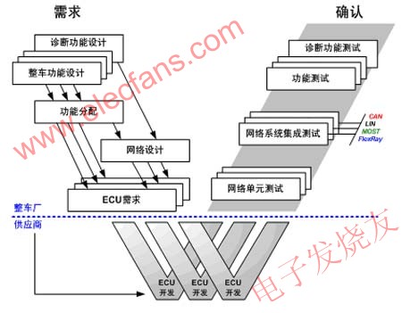
The network platform construction and network system development adopt the V-mode development process, as shown in the following figure. V mode defines a set of clear and effective development processes: OEMs complete the formulation of system requirements specifications and component requirements specifications from system requirements to component requirements, and issue component requirements specifications to suppliers; after the suppliers complete component development, The OEM then completes integration and verification on multi-wheel prototypes and prototypes from component testing to system testing.
Topology of bus network system
At present, the typical topology of passenger cars is shown in the figure below. The typical topology of commercial vehicles is similar to that of passenger cars, but because some commercial vehicles use both early and latest technologies, their topology has multiple gateways and the structure is relatively complex.
In addition, the speed of the MOST bus rose to 150 Mbit / s in 2008, and the BMW 7 series cars in 2009 have adopted the FlexRay bus. It is foreseeable that in the near future, MOST and FlexRay will replace the current infotainment CAN network and power CAN network.
Biomass Cook Stove,Wood Cook Stoves,Outside Camping Pellet Stove,Biomass Camping Stove
xunda science&technology group co.ltd , https://www.gasstove.be