
24-bit stereo CODEC technology designed by AK4953A
This article introduces the main features of the AK4953A, block diagrams, stereo and mono digital MIC connection cases, the system connection block diagram of the 3-wire serial connection mode, and the main features of the AKD4953-A evaluation board, block diagrams and circuit diagrams.
AK4953A is AKM's 24-bit stereo CODEC with integrated MIC / HP / SPK-AMP. The input circuit includes microphone amplifier and automatic volume control (ALC) circuit. The output circuit includes capacitorless headphone amplifier and speaker amplifier, integrated charge pump The circuit generates a negative voltage, so the output does not require AC coupling capacitors, and the operating voltage is 0.9V-5.5V. It is mainly used in portable devices with recording and playback functions.
AK4953A main features:
1. Recording FuncTIon
• Stereo Single-ended input with three Selectors
• MIC Amplifier (+ 29dB / + 26dB / + 23dB / + 20dB / + 16dB / + 12dB / 0dB)
• Digital ALC (AutomaTIc Level Control) (SetTIng Range: + 36dB ∼ −54dB, 0.375dB Step)
• ADC Performance: S / (N + D): 82dB, DR, S / N: 88dB (MIC-Amp = + 20dB) S / (N + D): 85dB, DR, S / N: 96dB (MIC-Amp = 0dB)
• Wind-noise ReducTIon Filter
• 5 Band Notch Filter
• Digital MIC Interface
2. Playback Function
• Digital De-emphasis Filter (tc = 50 / 15μs, fs = 32kHz, 44.1kHz, 48kHz)
• Digital ALC (Automatic Level Control) (Setting Range: + 36dB ~ −54dB, 0.375dB Step)
• Digital Volume Control (+ 12dB ~ −115dB, 0.5dB Step, Mute)
• Capacitor-less Stereo Headphone Amplifier
-HP-Amp Performance: S / (N + D): 80dB @ 24mW, S / N: 96dB
-Output Power: 24mW @ 16Ω
-Pop Noise Free at Power-ON / OFF
• Mono Speaker-Amplifier
-SPK-Amp Performance: S / (N + D): 70dB @ 250mW, S / N: 95dB
-BTL Output
-Output Power: 400mW @ 8Ω (SVDD = 3.3V) 100mW @ 8Ω (SVDD = 1.5V)
• Beep Generator
3. Power Management
4. Master Clock: (1) PLL Mode
• Frequencies: 11.2896MHz, 12MHz, 13.5MHz, 24MHz, 27MHz (MCKI pin) 32fs or 64fs (BICK pin) (2) External Clock Mode
• Frequencies: 256fs, 384fs, 512fs or 1024fs (MCKI pin) 5. Output Master Clock Frequencies: 32fs / 64fs / 128fs / 256fs
• PLL Slave Mode (BICK pin): 7.35kHz ~ 96kHz
PLL Slave Mode (MCKI pin): 7.35kHz, 8kHz, 11.025kHz, 12kHz, 14.7kHz, 16kHz, 22.05kHz, 24kHz, 29.4kHz, 32kHz, 44.1kHz, 48kHz, 64kHz, 88.2kHz, 96kHz
• PLL Master Mode: 7.35kHz, 8kHz, 11.025kHz, 12kHz, 14.7kHz, 16kHz, 22.05kHz, 24kHz, 29.4kHz, 32kHz, 44.1kHz, 48kHz, 64kHz, 88.2kHz, 96kHz
• EXT Master / Slave Mode: 7.35kHz ~ 96kHz (256fs), 7.35kHz ~ 48kHz (384fs), 7.35kHz ~ 48kHz (512fs), 7.35kHz ~ 12kHz (1024fs)
6. μP I / F: 3-wire Serial, I2C Bus (Ver 1.0, 400kHz Fast-Mode)
7. Master / Slave mode
8. Audio Interface Format: MSB First, 2's complement
• ADC: 24bit MSB justified, 16 / 24bit I2S
• DAC: 24bit MSB justified, 16bit LSB justified, 24bit LSB justified, 16 / 24bit I2S
9. Ta = −30 ∼ 85 ° C (SPK-Amp = OFF) Ta = −30 ∼ 70 ° C (SPK-Amp = ON)
10. Power Supply:
• Analog Power Supply (AVDD): 2.85 ~ 3.5V
• Digital Power Supply (DVDD): 1.6 ~ 2.0V
• Digital I / O Power Supply (TVDD): DVDD ~ 3.5V
• Speaker Power Supply (SVDD): 0.9 ~ 5.5V
11. Package: 36pin QFN (5 x 5mm, 0.4mm pitch) 
Figure 1. AK4953A block diagram
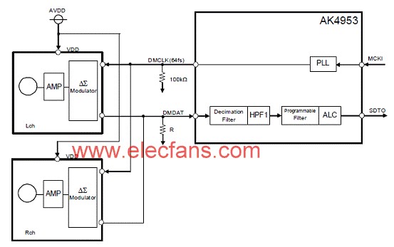
Figure 2. AK4953A stereo digital MIC connection case block diagram 
Figure 3. AK4953A mono digital MIC connection case diagram 
Figure 4. AK4953A system connection block diagram (3-wire serial connection mode)
AKD4953-A Evaluation Board
The AKD4953-A is an evaluation board for the AK4953 24bit CODEC with built-in PLL and MIC / HP / SPK Amplifier. The AKD4953-A has the interface with AKM's A / D evaluation boards. Therefore, it's easy to evaluate the AK4953. The AKD4953-A also has the digital audio interface and can achieve the interface with digital audio systems via opt-connector.
AKD4953-A evaluation board features:
• Compatible with 2 types of interface
-Direct interface with AKM's A / D converter evaluation boards
-DIT / DIR with optical input / output
• BNC connector for an external clock input
• 10pin header for serial control interface 
Figure 5. Block diagram of the AKD4953-A evaluation board 
Figure 6. AKD4953-A evaluation board circuit diagram (1) 
Figure 7. AKD4953-A evaluation board circuit diagram (2) 
Figure 8. AKD4953-A evaluation board circuit diagram (3) 
Figure 9. AKD4953-A evaluation board circuit diagram (4) 
Figure 10. AKD4953-A evaluation board circuit diagram (5) 
Figure 11. AKD4953-A evaluation board circuit diagram (6)
Two-axis Stabilizer is composed of rolling axis and tilt-axis. With a gyro-stabilized gimbal system, it reduces the movements when you are moving to shoot a smooth video.
2 axis gimbal stabilizer can be divided into 2 parts, including Two-Axis Stabilizer smartphone stabilizer and 2axis motion camera stabilizer.

Wewow focusing on handheld stabilizer is a technology company which does R & D independently. With Wenpod series product released, the company achieved the industry's praise and quickly became the leader of the smart stabilizer industry.
Our service
1. Reply to you within 24 hours.
2. Already sample: within 1-2days.
3. Shipping date: within 24 hours once get the payment.
4. 12 months warranty.
5. After-sales service, solve within 3 working dates.
If you have any questions, please contact with us directly.
Wewow appreciates domestic and international business relationship!
Two-axis Stabilizer
Two-Axis Stabilizer,Popular Two-Axis Stabilizer,Professional Two-Axis Stabilizer,Handheld Two-Axis Stabilizer
GUANGZHOU WEWOW ELECTRONIC CO., LTD. , https://www.stabilizers.pl