
Design of fuel cell electric vehicle controller based on MC9S12DP256
The fuel cell electric vehicle controller VCU (VehicleControlUnit) is the core control component of the whole car. It collects the accelerator pedal signal, the brake pedal signal and other component signals, and makes corresponding judgments to control the components of the lower layer controller. Action, driving the car to run normally. Therefore, the advantages and disadvantages of the VCU directly affect the performance of the vehicle.
This article refers to the address: http://
The development of the fuel cell electric vehicle controller is one of the key unit technologies for the national electric vehicle major project during the 10th Five-Year Plan period. The basic research of these key unit technologies is of great significance for seizing the commanding heights of the new generation of electric vehicles and promoting the leap-forward development of China's automobile industry.
1 fuel cell electric vehicle structure
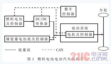
The fuel cell electric vehicle structure block diagram is shown in Figure 1. It consists of the vehicle controller, fuel cell and its controller, nickel-metal hydride battery pack and its controller, drive system, wheels and other components. Each component passes CAN (ControllerAreaNetwork). The bus forms a distributed control system. The fuel cell electric vehicle adopts the form of main and auxiliary dual power sources: the fuel cell as the main power source provides the main driving force for the car; the nickel-hydrogen battery pack is the auxiliary power source, which plays the role of “shaving the peak and filling the valley†in the driving of the car.
2 vehicle controller hardware function circuit design
2.1 Analysis of the functional requirements of the vehicle controller
The vehicle controller is equivalent to the brain of the car. It performs a number of tasks while the car is running. The specific functions include: (1) receiving and processing the driver's driving operation instructions, and sending control commands to the various component controllers to make the vehicle Drive as expected. (2) Reliable communication with motors, DC/DC, nickel-metal hydride battery packs, etc., through the CAN bus (and analog data of key information) for state acquisition and input and control command output. (3) Receiving and processing the information of each component, and providing the current energy status information in combination with the energy management unit. (4) Judgment and storage of system faults, dynamic detection of system information, and recording of faults. (5) It has a protection function for the whole vehicle, and classifies the whole vehicle according to the type of fault. In an emergency, the generator can be turned off and the high voltage system of the busbar can be cut off. (6) Coordinate and manage other electrical equipment on the vehicle.
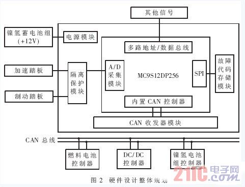
For the specific functions of the vehicle controller, the overall hardware design planning, MCU selection and design of each functional circuit are shown in Figure 2.
2.2 MCU selection
MCU is the core of the vehicle controller. It is responsible for data acquisition and processing, logic operation and control implementation. The selection of MCU is the most important task in the whole hardware design process. Motorola's HCS12 series 16-bit single-chip MC9S12DP256 has superior performance in terms of computing power, storage space, digital analog input and output, and CAN communication, and has high cost performance, making it ideal for some medium and high-end cars. Electronic control system.
This MCU has many features such as strong budget, large storage space and rich interface resources:
(1) Using STAR12CPU, the core computing power can reach 50MHz, the bus speed can reach 25MHz, and the optimized instruction set is used to greatly improve the operation speed of the instruction.
(2) The integrated 256KB FLASH, 12KBRAM and 4KBE2PROM on-chip can fully meet the requirements of the program for storage space.
(3) Many external interfaces, including five CAN interfaces compatible with CAN2.0A/B protocol, two asynchronous serial communication interfaces, three synchronous serial communication interfaces, sixteen 10-bit A/D interfaces, one I2C bus Interface, 49 independent digital I/O ports (20 of which have external interrupt and wake-up functions), 8-channel input capture/output comparison, etc.
2.3VCU hardware circuit design
The vehicle controller is a complex system in which multiple input, multiple output, and digital-to-analog circuits coexist, and each functional circuit is relatively independent. Therefore, according to the modular idea, each module of the hardware system is designed, including: minimum application system module, power module, CAN communication module, serial communication module, digital-to-analog input and output module.
2.3.1 Power Module
The power supply for the vehicle controller comes from the nickel-metal hydride battery pack of the fuel cell electric vehicle, and its calibration voltage is +12V. During the operation of the car, the voltage of the nickel-metal hydride battery pack is unstable and fluctuates very much, reaching +17V at high voltage and +9V at low voltage. The instability of the power supply voltage will directly cause the vehicle controller to work abnormally. Therefore, in the design process of the power module, a DC/DC power chip with a wide input range, high output precision, and high power is used. In addition, since the power supply voltage of the chip used in the vehicle controller includes +5V and +12V, two DC/DC chips are used in design: Infineon's TLE4270 and NationalSemiconductor's LM2940S-12, which have 12V respectively. -12V and 12V-5V transformer voltage regulation, and has short-circuit, over-voltage, over-current and temperature overload protection. By using these two chips and some auxiliary circuits (mainly filter circuits) on the periphery, the power supply module is stable and reliable.
2.3.2 CAN communication module
Since the MC9S12DP256 integrates five CAN modules compatible with CAN2.0A/B protocol, the CAN communication module of the vehicle controller does not need to add an off-chip CAN controller, and only needs to add a CAN transceiver. The designed CAN communication module uses PHILIP's TJA1040 transceiver chip. The chip's baud rate ranges from 60kbps to 1Mbps. It has a temperature protection circuit that disconnects the transmitter when the temperature at the connection point to the transmitter exceeds approximately 165°C (this is required when the bus is shorted). Temperature protection circuit) [2].
In order to enhance the anti-interference ability of the CAN bus node, the CANTXD and CANRXD pins of the main chip are not directly connected to the TXD and RXD pins of the TJA1040, but are connected to the TJA1040 through the high-speed optocoupler HCPL-0630. Thus, when there are multiple CAN nodes on the bus, electrical isolation between the CAN nodes can be achieved. The interface between TJA1040 and CAN bus also takes certain safety and anti-interference measures:
(1) The CANH and CANL pins of TJA1040 are connected to the CAN bus through a 5Ω resistor. The resistor can play a certain current limiting function to protect the TJA1040 from overcurrent.
(2) Two 30pF small capacitors are connected in parallel between CANH and CANL and ground, which can filter out high frequency interference on the bus and have certain anti-electromagnetic radiation capability.
(3) A protection diode is connected between the two CAN bus access terminals and the ground. When the CAN bus has a high negative voltage, the short circuit of the diode can provide a certain overvoltage protection.
2.3.3 Digital-to-analog input and output module
During the operation of the fuel cell electric vehicle, the vehicle controller often issues signals such as start/stop of the vehicle and closing/opening of the nickel-hydrogen battery pack, that is, digital output. In order to ensure the signal is stable and reliable, the vehicle controller has four digital outputs, and both are greater than 50mA. The design uses a relay-type switching output, which is currently the most commonly used output method. The relay chip used is Infineon's BTS824R, which has the following characteristics [3]:
(1) Wide voltage range input, compatible with CMOS and TTL levels.
(2) Enhanced electromagnetic compatibility design.
(3) Self-contained short circuit protection, overload protection, ESD protection.
(4) Self-contained over-temperature protection.
The vehicle controller also receives the corresponding digital signal while emitting the on and off signals. The high-speed optocoupler HCPL-0630 is connected between the main chip MC9S12DP256 and the external signal to realize level conversion and signal isolation.
The fuel cell electric vehicle controller VCU (VehicleControlUnit) is the core control component of the whole car. It collects the accelerator pedal signal, the brake pedal signal and other component signals, and makes corresponding judgments to control the components of the lower layer controller. Action, driving the car to run normally. Therefore, the advantages and disadvantages of the VCU directly affect the performance of the vehicle.
The development of the fuel cell electric vehicle controller is one of the key unit technologies for the national electric vehicle major project during the 10th Five-Year Plan period. The basic research of these key unit technologies is of great significance for seizing the commanding heights of the new generation of electric vehicles and promoting the leap-forward development of China's automobile industry.
1 fuel cell electric vehicle structure
The fuel cell electric vehicle structure block diagram is shown in Figure 1. It consists of the vehicle controller, fuel cell and its controller, nickel-metal hydride battery pack and its controller, drive system, wheels and other components. Each component passes CAN (ControllerAreaNetwork). The bus forms a distributed control system. The fuel cell electric vehicle adopts the form of main and auxiliary dual power sources: the fuel cell as the main power source provides the main driving force for the car; the nickel-hydrogen battery pack is the auxiliary power source, which plays the role of “shaving the peak and filling the valley†in the driving of the car.
2 vehicle controller hardware function circuit design
2.1 Analysis of the functional requirements of the vehicle controller
The vehicle controller is equivalent to the brain of the car. It performs a number of tasks while the car is running. The specific functions include: (1) receiving and processing the driver's driving operation instructions, and sending control commands to the various component controllers to make the vehicle Drive as expected. (2) Reliable communication with motors, DC/DC, nickel-metal hydride battery packs, etc., through the CAN bus (and analog data of key information) for state acquisition and input and control command output. (3) Receiving and processing the information of each component, and providing the current energy status information in combination with the energy management unit. (4) Judgment and storage of system faults, dynamic detection of system information, and recording of faults. (5) It has a protection function for the whole vehicle, and classifies the whole vehicle according to the type of fault. In an emergency, the generator can be turned off and the high voltage system of the busbar can be cut off. (6) Coordinate and manage other electrical equipment on the vehicle.
For the specific functions of the vehicle controller, the overall hardware design planning, MCU selection and design of each functional circuit are shown in Figure 2.
2.2 MCU selection
MCU is the core of the vehicle controller. It is responsible for data acquisition and processing, logic operation and control implementation. The selection of MCU is the most important task in the whole hardware design process. Motorola's HCS12 series 16-bit single-chip MC9S12DP256 has superior performance in terms of computing power, storage space, digital analog input and output, and CAN communication, and has high cost performance, making it ideal for some medium and high-end cars. Electronic control system.
This MCU has many features such as strong budget, large storage space and rich interface resources [1]:
(1) Using STAR12CPU, the core computing power can reach 50MHz, the bus speed can reach 25MHz, and the optimized instruction set is used to greatly improve the operation speed of the instruction.
(2) The integrated 256KB FLASH, 12KBRAM and 4KBE2PROM on-chip can fully meet the requirements of the program for storage space.
(3) Many external interfaces, including five CAN interfaces compatible with CAN2.0A/B protocol, two asynchronous serial communication interfaces, three synchronous serial communication interfaces, sixteen 10-bit A/D interfaces, one I2C bus Interface, 49 independent digital I/O ports (20 of which have external interrupt and wake-up functions), 8-channel input capture/output comparison, etc.
2.3VCU hardware circuit design
The vehicle controller is a complex system in which multiple input, multiple output, and digital-to-analog circuits coexist, and each functional circuit is relatively independent. Therefore, according to the modular idea, each module of the hardware system is designed, including: minimum application system module, power module, CAN communication module, serial communication module, digital-to-analog input and output module.
2.3.1 Power Module
The power supply for the vehicle controller comes from the nickel-metal hydride battery pack of the fuel cell electric vehicle, and its calibration voltage is +12V. During the operation of the car, the voltage of the nickel-metal hydride battery pack is unstable and fluctuates very much, reaching +17V at high voltage and +9V at low voltage. The instability of the power supply voltage will directly cause the vehicle controller to work abnormally. Therefore, in the design process of the power module, a DC/DC power chip with a wide input range, high output precision, and high power is used. In addition, since the power supply voltage of the chip used in the vehicle controller includes +5V and +12V, two DC/DC chips are used in design: Infineon's TLE4270 and NationalSemiconductor's LM2940S-12, which have 12V respectively. -12V and 12V-5V transformer voltage regulation, and has short-circuit, over-voltage, over-current and temperature overload protection. By using these two chips and some auxiliary circuits (mainly filter circuits) on the periphery, the power supply module is stable and reliable.
2.3.2 CAN communication module
Since the MC9S12DP256 integrates five CAN modules compatible with CAN2.0A/B protocol, the CAN communication module of the vehicle controller does not need to add an off-chip CAN controller, and only needs to add a CAN transceiver. The designed CAN communication module uses PHILIP's TJA1040 transceiver chip. The chip's baud rate ranges from 60kbps to 1Mbps. It has a temperature protection circuit that disconnects the transmitter when the temperature at the connection point to the transmitter exceeds approximately 165°C (this is required when the bus is shorted). Temperature protection circuit) [2].
In order to enhance the anti-interference ability of the CAN bus node, the CANTXD and CANRXD pins of the main chip are not directly connected to the TXD and RXD pins of the TJA1040, but are connected to the TJA1040 through the high-speed optocoupler HCPL-0630. Thus, when there are multiple CAN nodes on the bus, electrical isolation between the CAN nodes can be achieved. The interface between TJA1040 and CAN bus also takes certain safety and anti-interference measures:
(1) The CANH and CANL pins of TJA1040 are connected to the CAN bus through a 5Ω resistor. The resistor can play a certain current limiting function to protect the TJA1040 from overcurrent.
(2) Two 30pF small capacitors are connected in parallel between CANH and CANL and ground, which can filter out high frequency interference on the bus and have certain anti-electromagnetic radiation capability.
(3) A protection diode is connected between the two CAN bus access terminals and the ground. When the CAN bus has a high negative voltage, the short circuit of the diode can provide a certain overvoltage protection.
2.3.3 Digital-to-analog input and output module
During the operation of the fuel cell electric vehicle, the vehicle controller often issues signals such as start/stop of the vehicle and closing/opening of the nickel-hydrogen battery pack, that is, digital output. In order to ensure the signal is stable and reliable, the vehicle controller has four digital outputs, and both are greater than 50mA. The design uses a relay-type switching output, which is currently the most commonly used output method. The relay chip used is Infineon's BTS824R, which has the following characteristics [3]:
(1) Wide voltage range input, compatible with CMOS and TTL levels.
(2) Enhanced electromagnetic compatibility design.
(3) Self-contained short circuit protection, overload protection, ESD protection.
(4) Self-contained over-temperature protection.
The vehicle controller also receives the corresponding digital signal while emitting the on and off signals. The high-speed optocoupler HCPL-0630 is connected between the main chip MC9S12DP256 and the external signal to realize level conversion and signal isolation.
3 vehicle controller reliability design and testing
On the basis of perfect functions, the reliability of the vehicle controller is the main technical indicator of its quality. In the working environment of the fuel cell electric vehicle controller, the bus current transmitted by the motor, the inverter and the nickel-hydrogen battery pack changes greatly (especially when the inverter performs high-frequency modulation), and the generated space electromagnetic interference is strong. In addition, the temperature range of the working space is wide and the vibration intensity is large. The above-mentioned various unfavorable factors may cause interference effects on the vehicle controller mainly in the following aspects:
(1) The data acquisition error is increased.
(2) The control state is out of order.
(3) The data is subject to interference.
(4) The program is malfunctioning.
In order to ensure the normal operation of the vehicle controller, the reliability design adopts a combination of component-level reliability design and system-level reliability design, which is embodied in: temperature range control of the chip, redundant design of components, System electromagnetic compatibility design, etc.
3.1 chip temperature range
In the design of the vehicle controller, most of the chip temperature range is automotive grade (-40 ° C ~ +125 ° C), and other very few chips choose industrial grade (-40 ° C ~ +85 ° C) for price reasons.
3.2 redundant design
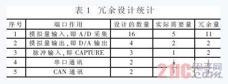
Redundant design refers to the technology that reduces the impact of faults by adding redundant resources to the system structure, or isolates faults and corrects errors, so that the function is still unaffected even if a fault or error occurs in the system [4] . This redundancy design is implemented by increasing the number of functional circuits, and the overall redundancy is more than 50%, as shown in Table 1.
3.3 Electromagnetic compatibility design
Because the application environment of the vehicle controller is harsh and the interference is serious, there are various noises and coupling modes, so the electromagnetic compatibility design plays an important role in all reliability design. Anti-interference technology such as filtering technology, decoupling circuit, shielding technology, isolation technology and grounding technology are adopted in the design [5][6], as follows:
(1) Select components with high integration. It can reduce the number of circuit board components, make the circuit board layout simple, reduce the pad and wiring, thus greatly reducing the probability of interference and increasing the anti-interference ability of the circuit board.
(2) Bold the power and ground lines, and the data lines, address lines, and control lines should be as short as possible to reduce the capacitance to ground.
(3) Digital circuit and analog circuit partitioning, and adding filtering and decoupling circuits.
(4) The design of the four-layer circuit board is adopted. Compared with the two-layer board, there are independent ground planes and power planes, and the signal line and ground line spacing can be very tight, so the common mode impedance and inductive coupling can be effectively reduced.
(5) Using copper plating technology. Both reducing the loop area (thus reducing the radiation) and reducing the crosstalk between the wires.
3.4 Reliability Test
The State Key Laboratory of Automotive Dynamic Simulation of Jilin University made a preliminary reliability test on the vehicle controller developed and designed. The test process is as follows:
(1) High and low temperature test: maintained at low temperature -25 ° C, high temperature 125 ° C for 6 hours.
(2) Vibration test: the scanning frequency range is 17-200 Hz, the maximum amplitude is 0.78 mm, the acceleration is 50 at 60-200 Hz, and the scanning time is 15 min.
(3) Electromagnetic compatibility test: use the real vehicle to simply simulate the electromagnetic interference conditions of various automobiles and do preliminary tests.
During the whole test process, the vehicle controller works normally, there is no reset phenomenon, and the function data sent and received by each function module is normal. During the vibration test, the components are not peeled off and damaged.
4 vehicle bench test
After the reliability test, the vehicle controller is connected with the fuel cell and its controller, the motor and its controller, the nickel-hydrogen battery pack and its controller to realize the power of the entire fuel cell electric vehicle. Assembly test bench. The following tests were performed on the gantry:
(1) Communication joint test: control system CAN communication test; signal acquisition of data monitoring system.
(2) Vehicle controller control logic test: According to the same driving mode as the actual vehicle, focus on the control logic single mode of acceleration mode, start mode, charging mode, regenerative braking mode, power battery charging mode and cruise driving mode. debugging.
(3) The vehicle controller controls the alarm test.
(4) Vehicle controller control mode switching test: focus on the switching between various control modes.
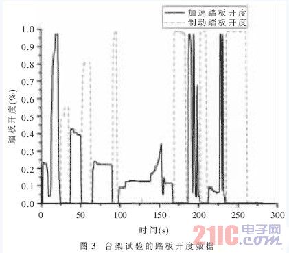
During the whole bench test and test, the vehicle controller runs stably, and each function module completes the task according to the specified program, and there is no reset and data loss. Figure 3 shows the pedal opening signal collected during the test, and the collected signal is continuous and complete. The vehicle controller not only achieves the stated goals in terms of functionality, but also meets the standards in terms of reliability.
The vehicle controller developed for the fuel cell electric vehicle not only achieves the required functions, but also has good reliability and engineering practicability. The design of some important circuit modules and the methods used in system reliability design have laid the foundation for the development of various types of electric vehicle controllers in the future.
Refrigeration Fan Motor is designed for cooling system , evaporative cooler etc. suit for hot weather environments. High quality winding with excellent insulation and heat transmission properties.Nice appearance , high starting torque, low starting current,smooth turning, low temperature rise, low vibration, low noise and great overload performance.Saving Energy , higher efficiency.Long life, Equipped with overheating protection , good Protection against Humidity.Special motors can be designed according to customer's requirement.Pure copper coil or copper clad aluminum coil can be choosed. Be wildly used in Iraq ,Sudan ,Iran ,Saudi and other gulf country market
Refrigeration Fan Motor
Refrigeration Fan Motor,Refrigerator Condenser Fan Motor,Refrigerator Evaporator Fan Motor,Refrigerator Fan Motor
ZHEJIANG ICE LOONG ENVIRONMENTAL SCI-TECH CO.,LTD. , https://www.ice-loong.com