
Industrial 16-bit DA converter composition principle
Circuit function
This article refers to the address: http://

The resolution of the 16-bit DA converter is 1/65535, which is equivalent to 0.0015% of the full-scale voltage, and 1LSB is the level of -96DB. So it can be used to produce high-precision waveforms or measurement flow control. The 1LSB of 10V full-scale is 152.6UV, which is close to the noise level, so the assembly problem should be considered when designing the circuit.
Circuit working principle
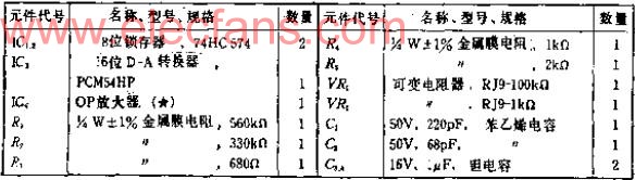
This circuit uses the inexpensive 16-bit DAC chip PCM54HP, which was developed for digital audio equipment. The data input is terminated with two 0 8-bit data latches, which are used to simultaneously input 16-bit data to reduce the noise caused by the time difference. If the DA conversion output does not require a high speed response, the latch can be removed and a low pass filter applied to the converter output.
The PCM54 is basically the same as a normal voltage output type DAC, and the output is a bipolar voltage of plus or minus 3 volts. In industrial applications, it is required to output positive or negative 5V or positive and negative 10V, so an amplifier A1 with a magnification of 3.3 times is added to the output. The most significant bit should be controlled externally. Linear and monotonically increasing performance is tuned with R1, R2 and variable resistor DR1.
The OP amplifier A1 can be selected according to the application. If it is used in a DC voltage generating circuit, a precision OP amplifier with small offset and drift can be selected. For waveform generators or digital audio circuits, devices with good AC characteristics should be used. This circuit has no offset adjustment circuit, which can be added as needed. The cutoff frequency of capacitors C1 and C2 is 1MHZ. For DC, the cutoff frequency should be reduced.
Component selection
The variable resistor VR1 of the most significant bit control circuit is narrowed down by a variable range after R1 and R2 are connected in series. VR1 is a stable device, and should be multi-turn type. All resistors are metal film resistors. Products with a small temperature coefficient should be used.
Adjustment
Although zero adjustment or full scale adjustment is convenient, the most effective position adjustment is difficult. Aligning VR1, measuring with a high-precision digital multimeter, and adjusting the 16-bit bit by bit in units of 1LSB is troublesome. If there are a large number of converters to be adjusted, the ROM with the digital sinusoidal data can be connected to the input end of the circuit, and the address is scanned by the ground counter, so that a sine wave can be generated, and VR1 can be adjusted to make the distortion meter The indicated distortion is minimal.
Assembly considerations
The 16-bit resolution DA or AD converter, because the voltage of the 1-bit is very small, the grounding of the logic power supply and the analog power supply should be clearly separated. When the digital data is used to generate a varying waveform at high speed, good grounding should be performed to avoid The lead of the input data is coupled to the summing junction of the OP amplifier A1 peripheral lead or DAC.
Network Cabinet is widely used for 19 inch network server enclosure perferated cabinet installing and placing of 19" international standard equipment and the system integration. Network Cabinets support large, modular network switches by providing additional space for cable management and side-to-side airflow solutions.
Network Cabinet
Network Cabinet,Electrical Cabinets,Wall Mount Server Cabinet,Wall Mount Server Cabinet,Wall Mount Cabinets,Electrical Distribution Cabinets
Sijee Optical Communication Technology Co.,Ltd , https://www.sijee-optical.com