
CAN physical layer debugging basic knowledge and examples
The Controller Area Network (CAN) standard is evolving and is being used in many new applications beyond automotive and industrial networks. Microprocessors that support it become commonplace and inexpensive, and the open source protocol stack makes it very easy to access and easy to add to new systems. There are many CAN boards available for BeagleBone (Capes), Stellaris (BoosterPacks), Arduino (Shields) and other microprocessor development platforms. What should I do when the designer's system is powered up but not working? This article introduces you to a better engineering method for debugging the CAN physical layer. We will introduce the basic debugging steps and explain the performance of a CAN physical layer and some tips for identifying the problem.
Debugging basics
The ISO11898-2 and ISO11898-5 specifications specify the high-speed CAN physical layer, the transceiver. Once you have mastered the basics of the CAN physical layer, you can quickly identify common problems with simple debugging tools. The basic laboratory tools required are an oscilloscope, a digital multimeter (DMM), and a power supply. If you want to understand the problem in depth, you need more accurate and more complex tools. This type of problem is beyond the scope of this article, but the basics presented here can help determine the category of the problem and other tools needed for further debugging. A CAN demonstration system assembled by TI and TI's SN65NVD255D Evaluation Module (EVM)1 for demonstration hardware. In addition, we used other things, such as the CAN connector outer connector cable and the chip hook (hold the transceiver pin and connect it to the cable to make it easier to connect the oscilloscope pointer, as shown in Figure 1).
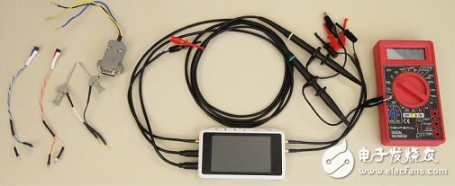
Figure 1: CAN physical layer debugging basic tools
Connection check
When starting the debug session, use the DMM to confirm the connection on the printed circuit board (PCB) as we expected - the system is not powered. This may seem basic, but surprisingly, this simple approach solves many simple problems. Everyone thinks that there are no problems with schematics, layouts, and manufacturing processes, but unfortunately they are sometimes not as desirable. Misplaced sub-boards, solder joints, incorrect terminations, or connected cables are common problems. Use the DMM resistor settings to verify that all lines and connections are correct. A simplified schematic of the CAN application shown in Figure 2 is used as a reference.
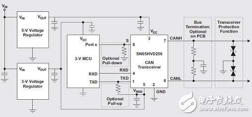
Figure 2: Simple schematic of the CAN application
Table 1 lists the PCB and network connections that need to be checked. The resistance between the transceiver pins and other related connections on the PCB should be 0Ω unless the design uses some of the options described in the table. For example, current-limiting series resistors, bus termination resistors, or pull-up or pull-down resistors for digital I/O.

Table 1: Summary of PCB and CAN Transceiver Connections
Bus termination check
Most CAN standards specify a single twisted pair (with or without shielding) with a characteristic impedance (Z0) of 120Ω. A resistor with the same characteristic impedance as the line should be used to terminate both ends of the cable to prevent signal reflections. The termination can be a single 120Ω resistor on the bus terminal of the cable, as shown on the left side of the CAN bus in Figure 3; or it can be located in a termination node, as shown on the right side of Figure 3. Do not remove the termination resistor from the bus. If the CAN termination resistor load does not exist, signal integrity will be affected and the bit timing requirements will not be met. If the bus common-mode voltage filtering and regulation are ideal, split termination is used, as shown in Figure 2. In this figure, each resistor is 60Ω and the split capacitor ranges from 1 nF to 100 nF, depending on the frequency required by the common mode filter. The measured resistance of 2CANH to CANL should be between 45Ω and 65Ω to achieve the CAN standard, the parallel impedance of the two termination resistors, and the tolerance of the input resistance of the parallel node. The rated power of the terminating resistor should be determined based on the extreme fault conditions that can be encountered (usually the supply voltage to the system ground).
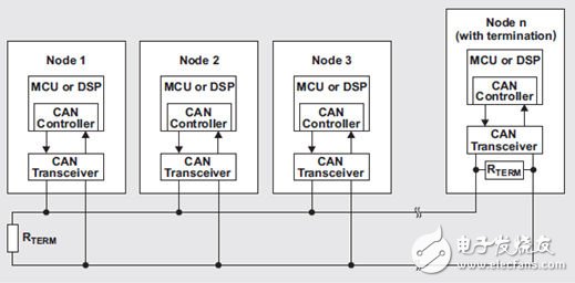
Figure 2: Simple schematic of the CAN application
Power check
Before powering up the system, first check one or more power supplies of the CAN transceiver. Depending on the type of transceiver used, VCC should be 3.3V or 5V. Regardless of whether you believe it or not, in some cases, losing VCC is indeed the root cause of the problem. Therefore, we should ensure that VCC is present on the VCC pin of the transceiver. Just check the DMM to confirm that there is a power supply. Care must be taken that the power supply is shorted to ground (unfortunately, this pin is next to the VCC pin).
The required current (ICC) difference between the dominant state (approximately 60 mA at 60 Ω bus load) and the recessive state (10 mA) is approximately 50 mA. The generation of the termination resistor differential voltage during the dominant bus state requires this 50 mA current difference and it varies with bus load variations. The DMM can also be used in current mode to verify the expected ICC supply current. Due to the switching nature of the CAN, the current measured by the DMM is pseudo-averaged.
It is recommended that the local bypass capacitor be at least 4.7μF to ensure adequate power supply buffering during bus state transitions. Otherwise, the inrush current of the transceiver may cause significant voltage supply ripple. We can use an oscilloscope to verify that the supply voltage is stable or that it changes as the bus state changes. During the conversion, it is best not to let the transceiver "starve". The transceiver is protected by its current limit, but when the transceiver attempts to drive the bus to a dominant state, if one of the buses is shorted to power or ground, the supply current is extremely high. If the voltage regulator is unable to supply so much current, the voltage level drops below the transceiver specification range and may even be as low as the undervoltage lockout state of the triggering transceiver.
How Ultrasonic Humidifier Work ?
Evaporative Cool Mist Humidifier rely on fans to blow air through their filters. On the other hand, Ultrasonic Air Humidifier, such as the DITUO Ultrasonic Humidifier, contain a small Atomizing plate that vibrates at an ultrasonic frequency. These ultrasonic sounds are inaudible to humans, but they're capable of some pretty powerful things. They can also break water particles from the humidifier's built-in reservoir apart into a cool vapor. The device then emits this fine mist into the air, instantaneously distributing humidity throughout the room.
Benefits of Ultrasonic
There are several reasons why Ultrasonic Cool Mist Humidifier are worth considering for your home.
- They're some of the quietest humidifiers around. Additionally, since ultrasonic humidifiers don't use heat, they require minimal electricity. This is perhaps one of the most major advantages of ultrasonics, because it can lead to significant savings on your bills in the long run.
- Aroma Diffuser Humidifier is easily portable, and can be instantly turned on and off. There's no waiting time for a heating element to boil the water, either, because the mist is produced through oscillation.
- Considering their relatively small size, Home Humidifier can produce impressive amounts of vapor. As such, they're an ideal option for maintaining proper moisture levels in smaller rooms.
Ultrasonic Humidifier
Ultrasonic Cool Mist Humidifier,Ultrasonic Humidifier,Ultrasonic Air Humidifier,Aroma Diffuser Humidifier
Shenzhen Dituo Electronic Co.,Ltd. , https://www.sz-dituo.com