
Labview-based remote temperature and humidity measurement and control system for flue-cured tobacco house
Labview-based remote temperature and humidity measurement and control system for flue-cured tobacco house
0 Preface
The curing process of tobacco leaves is a key step in producing high-quality tobacco leaves, and the quality of flue-cured tobacco is closely related to the temperature and humidity environment during the curing process. Tobacco farmers use alcohol or kerosene glass tube thermometers, using manual opening and closing return air doors (for moisture removal) and blowers (controlling furnace fire), the temperature measured is inaccurate, the control method is passive, and the operator is more than 5 consecutive days. Fatigue operation makes it a bottle diameter that restricts the improvement of tobacco leaf baking quality. Therefore, the remote measurement and control technology that uses electronic equipment to control the temperature and humidity of the roasting room has become an inevitable trend in the development of flue-cured tobacco technology. This paper introduces a design method of a remote intelligent measurement and control system based on virtual instruments in the flue-cured tobacco room to improve the temperature and humidity control accuracy and the quality of the flue in the flue-cured room. The system has the advantages of responsiveness, strong anti-interference ability, etc. Labor intensity.
1 System design
The blower and exhaust fan in the flue-cured tobacco room can adjust the indoor temperature and humidity respectively. The system adopts the time-sharing system in the computer to allocate time slices to each task of the multi-task to realize the detection and control of the temperature and humidity of multiple flue-cured tobacco rooms with one computer and one data card. Use the analog multi-channel switch in the data acquisition card to realize the switching between the various hardware data channels to achieve the purpose of time-slot sampling and control of each channel. This design method is suitable for the control of parameters that are not sensitive to time changes (such as temperature and humidity, etc.), and can reduce the complexity of the monitoring system. And can also use Remote Panel technology to achieve remote communication of the measurement and control system, as well as data release on the network. The system is composed of hardware and software, of which hardware is the foundation and software is the core.
2 hardware design
The hardware part of the system first converts the temperature and humidity signals into electrical signals, and transmits the conditioned data to the computer, and then the control signals are output by the acquisition card to control the temperature and humidity control devices. The hardware of the system is composed of temperature and humidity sensor, DAO card (data acquisition card), control circuit, blower and exhaust fan. Figure 1 shows a block diagram of the hardware structure.

2.1 Acquisition of temperature and humidity signals
The system uses a silicon single crystal temperature sensor and corresponding circuit to capture the temperature signal and convert the temperature signal into a voltage signal. At the same time, the UD-08 humidity sensor and corresponding circuit are used to capture the temperature signal and convert its humidity into a voltage signal. The block diagram of its composition is shown in Figure 2.

2.2 Control circuit
The working principle of the control circuit is that the electrical signal output by the sensor is amplified and filtered, and then enters the computer through the data acquisition card. The computer finds the deviation according to the actual temperature and humidity and the given temperature and humidity of the system, and uses the PID control algorithm to find the output control of the system Signal, and then output the control signal through the data acquisition card to control the action of the relay. Then control the operation of the blower and exhaust fan to adjust the temperature and humidity of the grill.
This system uses the NI company's data acquisition card PCI-6024. This card is designed based on the PCI bus and can support unipolar and bipolar analog signal input. The signal input ranges are -5 to +5 V and 0 to 10 V, respectively. . At the same time, PCI-6024 can also provide 16 single-ended / 8 differential analog input channels, 2 independent D / A output channels, 24-wire TTL type digital I / O, 3 16-bit timer counters and other functions Module. Using Measurement AutomaTIon software provided by NI company to set it up can achieve the communication between the system software and the data acquisition card.
The blower works at 220VAC, and it can be controlled by solid state relays. The working voltage of the exhaust fan is 12VDC, and it can be controlled by ordinary relays.
3 software design
This measurement system uses LabVIEW 7.0 Express as the control software. The LabVIEW program is called the virtual instrument program. It is a development environment based on the graphical programming language G and is a programming platform for instrument control and data acquisition. The LabVIEW program collects data by controlling the data acquisition card. The voltage analog signal is collected by the data acquisition card and then input into the computer. The PID algorithm is used to analyze and process the collected data. At the same time, the generated control signal is used to send the processed data to the output channel. The collection status of the system is displayed on the front panel, and the collected temperature and humidity data is saved in the form of a file. Modular programming idea divides the system into 4 modules: data acquisition, system control, real-time display, and data storage, and writes each module into a subVI, allowing each module to complete the determined task, and then calls each through the main program Sub VI.
3.1 Main control module
The main control module can enable each module to coordinate actions and communication according to the system's framework protocol and realize human-computer interaction functions. The main control module provides a user interface, and the main control module can respond to user instructions by scheduling each functional module. The system provides a vivid instrument soft panel for the convenience of users.
3.2 Data acquisition module
The function of the data acquisition module is to convert the temperature signal into a digital quantity and transfer it to the computer. The data acquisition function of NI's data acquisition card can be combined by the middle-level mold function in the mold module provided by LabVIEW.
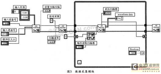
Figure 3 is a block diagram of a data acquisition program designed using mid-level mold-in. The program first uses the Device Open.vi module to open the data acquisition device; then uses the AI ​​Config.vi module to configure the data acquisition card. Select the analog input channel, specify the range of the input signal (adjust the hardware gain), set the size of the computer buffer occupied by the collected data, and set the scan interval: then start the mold-in operation through AI Start.vi, whose role is mainly to control data acquisition Rate and the number of scans to be obtained, here you can select the continuous acquisition mode by setting the value of the Number of scans to acquire input port to "0" until the mold-in operation is cleared (if set to "-1" Then stop scanning as long as the buffer is full); AI Read.vi's role is to read data from the buffer allocated by AI Config, it can control the number of points read each time, the position of the read data in the buffer, etc. The output is a two-dimensional array, where each column of data corresponds to a channel in the channel list; finally, the AI ​​Clear.vi module is used to clear the buffer allocated in the mold operation and computer, and release all data acquisition resources.
The system sends the collected data to the input port of the PID controller. After PID processing, the control output is output through the output channel of the data collection card.
3.3 System control module
The working principle of the control circuit is to amplify and filter the electrical signal output by the sensor, and then input it into the computer through the data acquisition card. The computer finds the deviation according to the actual temperature and humidity and the given temperature and humidity of the system, and uses the PID control algorithm to find the system Output control signal, and then control the action of the relay through the control signal output by the data acquisition card, and then control the work of the blower and exhaust fan, and finally achieve the purpose of adjusting the temperature and humidity of the flue-cured room.
The basic idea of ​​this module is: according to the three-stage roasting requirements of flue-cured tobacco, in different stages, the tobacco farmers first send the corresponding control commands on the front panel of the client VI to set the temperature and humidity parameters, and then the system The PID control algorithm is used for processing, and the corresponding control signals are generated through the data acquisition card to control the work of the related relays. PID is the most widely used algorithm in current industrial control. Figure 4 is the basic structure of a typical PID control system. Here, the system parameters to be controlled are called process variables (PV-Process variable), and the ideal values ​​specified by the controlled process variables are called setpoints (SP-setpoint). The PID controller first determines an output (U-output) to the controlled system, and then drives the process variable to approach the set point.

Taking temperature control as an example, when the temperature is lower than the set threshold range, the controller writes '1' to the corresponding bit of the digital I / O channel, and the control relay is turned on (the blower starts), and the temperature rises; otherwise, The controller writes '0' to the corresponding bit of the digital I / O channel, the relay closes (the blower stops), and the temperature decreases. Repeat this way to stabilize the temperature value within the threshold of the set value. Through practice, the floating range of temperature is set to ± 2 ℃, and the floating range of humidity is set to ± 3.5%.
3.4 Status display module
The main work completed by the temperature and humidity alarm module is to specify the range and corresponding status of the collected temperature and humidity signals, and to prompt the user visually or audibly in a more intuitive way. The system two-channel data status analysis module program is shown in Figure 5. The system uses InRange and Coerce.vi to determine the range of the collected data, and uses Select.vi to select the determination result. If the collected data is within the specified range, it displays "normal", otherwise it is in the "alarm" state, and the collected data and status can be Also displayed on the front panel. First, the farmers set the temperature and humidity parameters in advance at the beginning of the three stages of flue-cured tobacco, and then the program automatically uses the calculation of the addition and subtraction of graphic codes to obtain the upper and lower limits of temperature and humidity, to check the display data and status through the front panel at any time.

3.5 Data storage module
This module calls Write Characters ToFile in LabV IEW. The VI stores the processed temperature and humidity values ​​in the specified file for future analysis and research.
3.6 Network transmission module
This system uses LabVIEW's Remote Panel (RemotePanel) technology, without any programming, only need to set a few parameters in Lab-VIEW. This technology allows users to directly open and operate the front panel of a VI located on a remote (Web Server) computer on the local (Client) computer, and even embed the front panel window of LabVIEW into a web page and directly operate it on the web page. , The operation is extremely simple.
When using Remote Panel in LabVIEW, you need to complete the two steps of starting the Lab-VIEW Web Server service on the LabVIEW Web Server computer and connecting and running the Remote Panel on the Client computer.
At present, there are two ways to implement RemotePanel operation on the client computer: one is to directly operate the Remote Panel in the LabVIEW environment; the other is to use the web browser to directly operate the Remote Panel in the webpage. This system uses the first technique. Before using Remote Panel on the client side, first run LabVIEW on the Server computer and configure the Web Server to complete the file path and network settings. Client access authority settings, VIs access authority settings. After that, you can run a Remote Panel in the IabVIEW environment on the client side. Specific steps are as follows:
(1) Open the front panel of the VI to be run remotely on the Web Server:
(2) Select Operate → Connect to Remote Panel in the menu bar in the LabVIEW environment on the client side, and then enter the IP address and the name and port number of the opened VI in the pop-up Connect to Remote Panel dialog box.
(3) Click the Connect button to connect, Remote Panel will appear on the screen, but the client-side front panel and WebServer-side front panel are different, and the client-side front panel can be operated and controlled.
4 Conclusion
This system is based on LabVIEW 7.0 function software, which realizes the remote monitoring and control of multiple flue-cured tobacco rooms with a computer and a data acquisition card, thereby improving the accuracy of temperature and humidity measurement and control and the quality of flue-cured tobacco in the flue-cured room, and reducing the labor intensity of tobacco farmers . Therefore, the development and application of this system will greatly overcome the shortcomings of the complicated hardware structure and troublesome software programming of the traditional microcontroller-based monitoring system.
Vacuum Cleaner Bldc Dry Motor,Vacuum Cleaner Bldc Motor,Dry Bldc Motor For Vacuum Cleaner,Bldc Brushless Motor Vacuum Cleaner
Zhoushan Chenguang Electric Appliance Co., Ltd. , https://www.vacuum-cleaner-motors.com