
Analysis of a Coplanar Waveguide Feeding Broadband Circularly Polarized Square Slot Antenna
Since printed wide slot antennas have the advantages of wideband impedance, single metal layer and easy integration with active circuits, they are increasingly used in designing circularly polarized antennas with increased axial ratio. By designing a perturbation structure in a square slot, such an antenna can achieve a wider axial ratio bandwidth. The perturbation structure includes loading a cross-shaped patch, a T-shaped floor metal strip, a pair of L-shaped floor metal guide strips, or extending an L-shaped adjustable branch section and a pair of floor guide strips from the feed line.
The perturbation structure of the broadband circularly polarized slot antenna proposed in this paper is to load an E-shaped slot on the square conduction band of the two corners of the floor. The 3 dB axial ratio bandwidth can be adjusted by changing the length of the intermediate slot of the E-shaped slot. The optimal 3 dB axis ratio is up to 32.8%, the corresponding center frequency is 2165 MHz, and the impedance bandwidth of VSWR ≤ 2 can reach 54.8%.
2 antenna structure The proposed circularly polarized slot antenna is shown in Figure 1. The antenna is printed with a side length of G=60 mm and a dielectric constant of  , thickness is h=1.6 mm, loss tangent is
  On the square FR4 substrate. Using a 50 om coplanar waveguide feed, the length of the feed line and the width of the gap are Wf = 4 mm and g = 0.5 mm, respectively. The length of the radiating element that protrudes into the gap is Lt+g, and the line length of the back Lt is Wt=8 mm. The two square floors on the opposite side of the floor are L2=15 mm long, and E-shaped slits are loaded on the two square conduction bands to realize broadband circularly polarized radiation. The length and width of the E-shaped slit are designed to be L=14 mm, and the length of the intermediate slit is Ls. Changing Ls can adjust the 3 dB axial ratio of the antenna without affecting the impedance bandwidth of the antenna. Each of the narrow slits constituting the E-shaped slit has a width of W = 1 mm. The illustrated structure will excite left-handed and right-hand circularly polarized waves in the +z and -z directions, respectively.
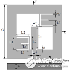
Figure 1 Antenna structure diagram
If the two square floors and the E-shaped slit on the diagonal are changed to the other two diagonals, the right-handed and left-handed circularly polarized waves will be excited in the +z and -z directions.
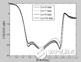
Fig. 2 Simulation curve of return loss of antenna with different size of Ls
3 Simulation and experimental resultsTo illustrate that the 3 dB axial ratio of the antenna can be adjusted by Ls, first study the characteristics of the antenna when Ls = 0 mm. Using the electromagnetic simulation software Ansoft HFSS simulation, the center frequency is 2315.5MHz, the 3 dB axis ratio bandwidth is 26.5%, and the VSWR ≤ 2 impedance bandwidth is 57% (1420-559 MHz). When Ls is increased to Ls=7mm, the 3dB axial ratio bandwidth is increased to 31.4%, the center frequency is reduced to 2113 MHz, and the impedance bandwidth of VSWR≤2 is unchanged, still 1420-2559 MHz. As Ls increases to Ls=8 mm, ideal simulation results can be achieved. The 3 dB axis ratio bandwidth is increased to 33.4%, the center frequency is reduced to 2088 MHz, and the impedance bandwidth of VSWR ≤ 2 remains unchanged. When Ls is increased to Ls = 10 mm, the 3 dB axis ratio of the antenna is 32.2%, and the impedance bandwidth of VSWR ≤ 2 is 1420-2559 MHz. The structural parameters and simulation results of the corresponding antennas for different sizes of Ls are shown in Table 1. Figure 2 shows the corresponding return loss simulation curves for different sizes of Ls. Figure 3 shows the corresponding axial ratio simulation curves for different sizes of Ls. The simulation results show that Ls can easily adjust the 3 dB axial ratio bandwidth of the antenna, but it does not affect the impedance bandwidth of VSWR≤2.
Table 1 shows the structural parameters of the antenna in different sizes of Ls, the simulated 3 dB axial ratio bandwidth and the simulated VSWR ≤ 2 impedance bandwidth. The parameters are: 
 , where the center frequency is the center frequency of the 3 dB axis ratio bandwidth
Ls (mm) axis ratio center
Frequency MHz3 dB AR bandwidth
MHz, %VSWR ≤ 2 impedance bandwidth MHz, %
02315.52009-2622, 26.5%1420-2559, 57%
721131781-2445, 31.4% 1420-2559, 57%
820881739-2437, 33.4% 1420-2559, 57%
102242.51881-2604, 32.2% 1420-2559, 57%
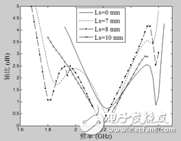
Fig. 3 Simulation of the axial ratio of the antenna with different dimensions of Ls
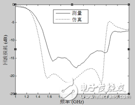
Figure 4: Return loss measurement curve of antenna when Ls=8 mm
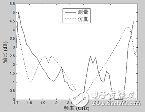
Figure 5 Axis ratio measurement curve of antenna when Ls=8 mm

Figure 6 Antenna at the axial center frequency when Ls = 8 mm
Xoz face pattern measured at 2165 MHz
Figure 4-5 shows the return loss measurement curve and the axial ratio measurement curve of the antenna at Ls=8 mm. As can be seen from the figure, the antenna has a VSWR ≤ 2 impedance bandwidth of 1510-2650 MHz (54.8%), an axial ratio bandwidth of 1810-2520 MHz (32.8%), and a corresponding center frequency of 2165 MHz. The measured axial ratio curve and return loss curve are in agreement with the simulation results. Figure 6 is a xoz plane pattern of the antenna measured at the shaft center frequency at Ls = 8 mm. The antenna antenna realizes left-hand and right-hand circular polarization characteristics in the +z and -z directions, respectively. Figure 7 shows the gain measurement curve of the antenna in the circularly polarized bandwidth at Ls = 8 mm. In the circularly polarized radiation band, the gain of the antenna can be up to 5 dB and the minimum can be achieved by 3.5 dB. Figure 8 is a physical diagram of the antenna processed at Ls = 8 mm.
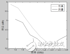
Figure 7 Measurement gain of the antenna in a circularly polarized bandwidth at Ls = 8 mm
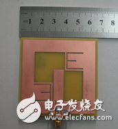
Figure 7 Antenna map of Ls=8 mm
4 ConclusionIn this paper, a new coplanar waveguide fed broadband circularly polarized square antenna is proposed. The measured axial ratio bandwidth exceeds 32%, and the VSWR ≤ 2 impedance bandwidth reaches 54.8%. And the axial specific bandwidth can be conveniently adjusted by the length of the intermediate slit of the E-shaped slit. The antenna achieves good left-hand and right-hand circular polarization characteristics in the +z and -z directions, respectively.
Dongguan Guancheng Precision Plastic Manufacturing Co., Ltd. , https://www.dpowergo.com