
ST company's STM8AF5286 main features and block diagram
ST's STM8AF5286 is an 8-bit MCU for automobiles equipped with up to 128KB of flash memory, data EEPROM, 10-bit ADC, timer, LIN, CAN, USART, SPI, I2C, etc., operating voltage 3-5.5V, STM8 The CPU core adopts Harvard architecture and three-stage pipeline, and the operating frequency is up to 24MHz. It is evaluated by STM8A-DISCOVERY kit. This article introduces the main features of STM8AF5286, block diagram, and main features of STM8A-DISCOVERY Discovery development board, hardware block diagram of STM8AF board and STM8AL board, circuit diagram And bill of materials.
The STM8AF526x/8x/Ax and STM8AF6269/8x/Ax automoTIve 8-bit microcontrollers described in this datasheet offer from 32 Kbyte to 128 Kbyte of non volaTIle memory and integrated true data EEPROM. They are referred to as high density STM8A devices in STM8S series And STM8AF series 8-bit microcontrollers reference manual (RM0016).The STM8AF52 series features a CAN interface.
All devices of the STM8A product line provide the following benefits: reduced system cost, performance and robustness, short development cycles, and product longevity.
The system cost is reduced thanks to an integrated true data EEPROM for up to 300 k write/erase cycles and a high system integraTIon level with internal clock oscillators, wtachdog, and brown-out reset.
Device performance is ensured by 20 MIPS at 24 MHz CPU clock frequency and enhanced characterisTIcs which include robust I/O, independent watchdogs (with a separate clock source), and a clock security system.
Short development cycles are guaranteed due to application scalability across a common family product architecture with compatible pinout, memory map, and modular peripherals. Full documentation is offered with a wide choice of development tools.
Product longevity is ensured in the STM8A family thanks to their advanced core which is made in a state-of-the art technology for automotive applications with 3.3 V to 5.5 V operating supply.
All STM8A and ST7 microcontrollers are supported by the same tools including STVD/STVP development environment, the STice emulator and a low-cost, third party in-circuit debugging tool.
Main features of STM8AF5286:
Core
– Max fCPU: 24 MHz
– Advanced STM8A core with Harvard architecture and 3-stage pipeline
– Average 1.6 cycles/instruction resulting in 10 MIPS at 16 MHz fCPU for industry standard benchmark
Memories
– Program memory: 32 to 128 Kbyte Flash program; data retention 20 years at 55 °C
– Data memory: up to 2 Kbyte true data EEPROM; endurance 300 kcycle
– RAM: 6 Kbyte 
Clock management
– Low-power crystal resonator oscillator with external clock input
– Internal, user-trimmable 16 MHz RC and low-power 128 kHz RC oscillators
– Clock security system with clock monitor 
Reset and supply management
– Wait/auto-wakeup/Halt low-power modes with user definable clock gating
– Low consumption power-on and power-down reset 
Interrupt management
– Nested interrupt controller with 32 vectors
– Up to 37 external interrupts on 5 vectors 
Timers
– 2 general purpose 16-bit timers with up to 3 CAPCOM channels each(IC, OC, PWM)
– Advanced control timer: 16-bit, 4 CAPCOM channels, 3 complementary outputs, dead-time insertion and flexible synchronization
– 8-bit AR basic timer with 8-bit prescaler
– Auto-wakeup timer
– Window and independent watchdog timers
I/Os
– Up to 68 user pins (11 high sink I/Os)
– Highly robust I/O design, immune against current injection
ï‚· Communication interfaces
– High speed 1 Mbit/s CAN 2.0B interface
– USART with clock output for synchronous operation - LIN master mode
– LINUART LIN 2.2 compliant, master/slave modes with automatic resynchronization
– SPI interface up to 10 Mbit/s or fMASTER/2
– I2C interface up to 400 Kbit/s 
Analog to digital converter (ADC)
– 10-bit resolution, 2 LSB TUE, 1 LSB linearity and up to 16 multiplexed channels 
Operating temperature up to 150 °C 
Qualification conforms to AEC-Q100 grade 0

Figure 1. STM8AF526x/8x/Ax and STM8AF6269/8x/Ax block diagrams
STM8A-DISCOVERY Discovery Development Board
The STM8A-DISCOVERY helps you discover the STM8AF and STM8AL automotive
The microcontroller family features and develop your applications through two dedicated application boards that can be connected together via a LIN network.
The STM8AF board can perform both CAN and LIN communications with the MCU poweredat 5 V and is ready to be connected into a network with its integrated transceiver.
The STM8AL board manages LIN slave communication through its transceiver and uses a 4-digit alphanumeric LCD display with the MCU powered at 3.3 V, offering low energy powermodes.
Both STM8AF and STM8AL boards include push buttons, LEDs, external connectors and allow various configurations to take advantage of the numerous capabilities of themicrocontrollers.
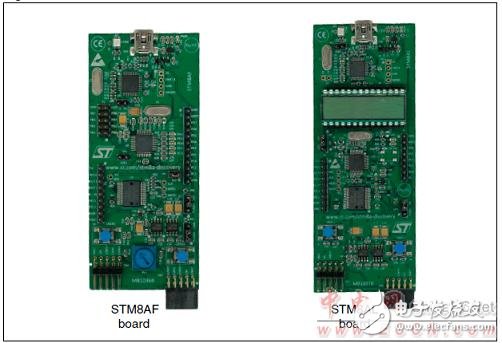
Figure 2. Outline drawing of the STM8A-DISCOVERY Discovery development board
Common features of STM8AF and STM8AL board:
â— On-board ST-LINK/V2 included for debugging and programming
â— Board power supply: through 5 V USB bus
â— Internal dual ST662A step-up converter building the 12 Vdc when powered by USBport
â— External application power supply VBAT (up to 14 Vdc)
â— 16 MHz HSE XTAL crystal oscillator
â— L99PM62GXP power management IC with LIN and high speed CAN with SPI control
Interface and high-side drivers
â— Two push buttons (USER1 and USER2)
â— Extension header for L99PM62GXP including relays, high-side outputs and wake-up
Capabilities
STM8AF board features:
â— STM8AF5288T microcontroller featuring 64 Kbytes Flash, 2 Kbytes data EEPROM,
LIN, CAN in an 48-pin package
â— Seven LEDs:
– LD1 (red/green) for USB communication
– LD2 (red) for 5 V power ON
– Five user LEDs LD3 (red) and LD4 to LD7 (green)
â— RV1 potentiometer connected to the ADC peripheral
â— Extension headers for MCU connectivity (full Port B, free ports pins, RESET)
STM8AL board features:
â— STM8AL3L68T microcontroller featuring 32 Kbytes Flash, 1 Kbytes data EEPROM,
LCD in an 48-pin package
â— Four LEDs:
– LD1 (red/green) for USB communication
– LD2 (red) for 3.3 V power ON
– 2 user LEDs LD3 (red) and LD4 (green)
â— 4-digit alphanumeric LCD display including 4 bars display
â— Extension header for MCU connectivity (free ports pins, RESET)
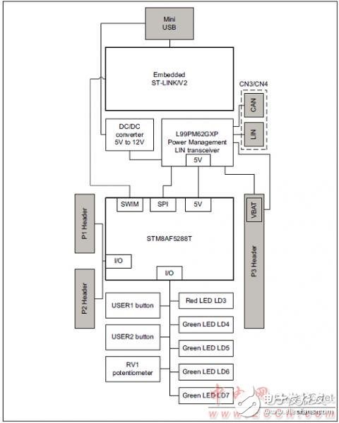
Figure 3. Hardware block diagram of the STM8AF board
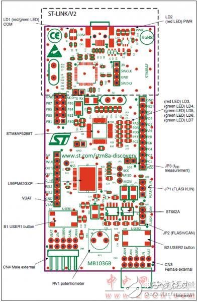
Figure 4. Front layout of the STM8AF board
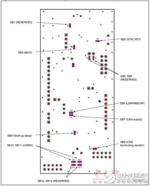
Figure 5. Rear layout of the STM8AF board
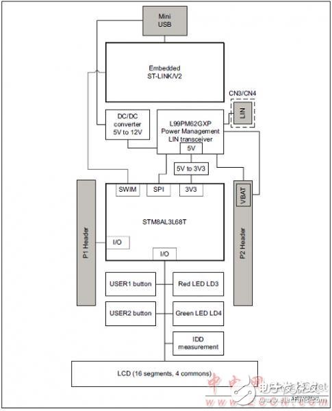
Figure 6. Hardware block diagram of the STM8AL board
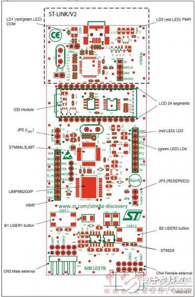
Figure 7. Front layout of the STM8AL board
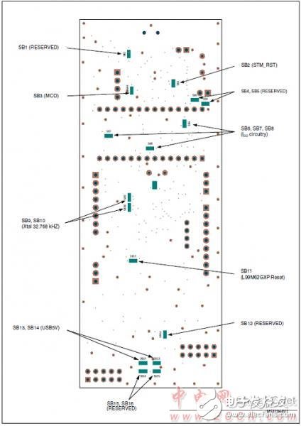
Figure 8. Rear layout of the STM8AL board
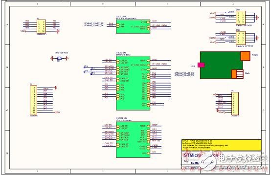
Figure 9. STM8AF board circuit diagram (1)
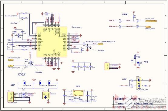
Figure 10. STM8AF board circuit diagram (2): ST-LINK/V2 (SWIM only)

Figure 11. STM8AF board circuit diagram (3): MCU
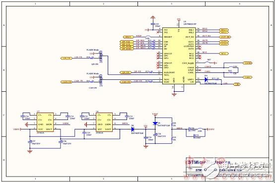
Figure 12. STM8AF board circuit diagram (4): CAN/LIN and 12V

Figure 12. STM8AL board circuit diagram (1)

Figure 13. STM8AL board circuit diagram (2): ST-LINK/V2 (SWIM only)
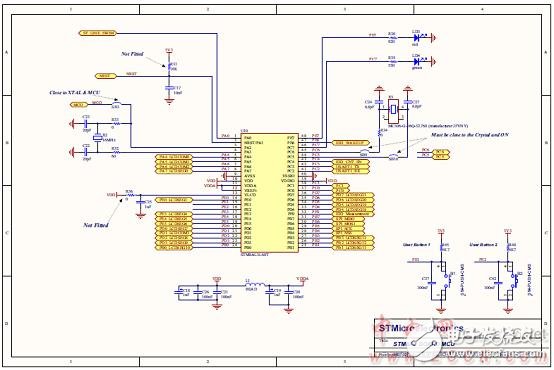
Figure 14. STM8AL board circuit diagram (3): MCU
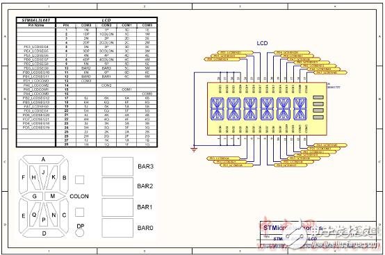
Figure 15. STM8AL board circuit diagram (4): LCD
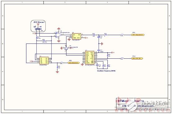
Figure 16. STM8AL board circuit diagram (5): IDD measurement
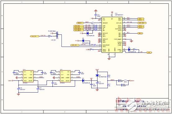
Figure 17. STM8AL board circuit diagram (5): LIN and 12V
Prism, a transparent object surrounded by two intersecting planes that are not parallel to each other, used for splitting or dispersing light beams. Prism is a polyhedron made of transparent materials (such as glass, crystal, etc.). It is widely used in optical instruments. Prisms can be divided into several types according to their properties and applications. For example, in spectral instruments, the "dispersion prism" that decomposes the composite light into spectrum is more commonly used as equilateral prism; In periscope, binocular telescope and other instruments, changing the direction of light to adjust its imaging position is called "total reflection prism", which generally adopts right angle prism.

Optical Prisms,Right Angle Prism,Penta Prism,Paul Prism
Hanzhong Hengpu Photoelectric Technology Co.,Ltd , https://www.hplenses.com